Introductory Circuit Analysis (13th Edition)
13th Edition
ISBN: 9780133923605
Author: Robert L. Boylestad
Publisher: PEARSON
expand_more
expand_more
format_list_bulleted
Question

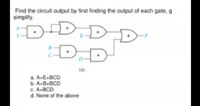
Transcribed Image Text:Find the circuit output by first finding the output of each gate, g
simplify.
D-DI
D.
(a)
a. A-E+BCD
b. A.B.BCD
C. A+BCD
d. None of the above
Expert Solution
This question has been solved!
Explore an expertly crafted, step-by-step solution for a thorough understanding of key concepts.
Step by stepSolved in 2 steps with 2 images

Knowledge Booster
Learn more about
Need a deep-dive on the concept behind this application? Look no further. Learn more about this topic, electrical-engineering and related others by exploring similar questions and additional content below.Similar questions
- (a) Consider the flipflop circuits below: (i) Name the 2 circuits given in the figure. Explain how they are different from each other. a. b. (ii) Choose from the list the input that triggers data to travel to the next flipflop in a counter. A: Input at top NAND gate B: Input at bottom NAND gate C: Clock input clk Qarrow_forward1. PLEASE EXPLAIN IN WRITING THE STEPS AND WHAT IS GOINING ONarrow_forward8-LEDS are connected to PORTC of an AVR ATmega16 microcontroller. Write a program to control the LEDS to behave in a sequence as shown in the figure toggling at each interval of 800ms delay time state and stepping to return back in the same sequence to initial state looping for 6 times 00arrow_forward
- Which circuit would cause this output signal given this input signal? Input signal Vi Output signal Vo time time R y ww A. В. R2 C. D.arrow_forward2a) What is the output of a two input AND gate when both inputs are LOW? 2b) What is the output of a two input AND gate when both inputs are HIGH? 2c) What is the output of a two input OR gate when both inputs are LOW? 2a What is the output of a three input OR gate when two inputs are HIGH and the third input is LOW? 2bWhat is the output of a NOT gate when the input is LOW?arrow_forwardFigure below shows a 4-input OR gate built using a chain of gates. Determine the activity factors at each node in the circuit assuming the input probabilities PA= PB = Pc = PD=0.5. C D an am P = am Domz an am ng aarrow_forward
- Need correct answer asap with explaination.arrow_forwardOften it is useful to model complex chips as simple linear equivalent models to determine the effects of the current draw and to ensure safe operation of the circuit. Consider the circuit shown in figure 5, it is a model of a digital microprocessor circuit. Each current source represent the current drawn by a portion of a digital circuits in the microprocessor. The resistors represent the power distribution network from the supply to that portion of the processor. Each current source can only have the following values: either be off i.e. 0 or have a value of I.. The reason being digital circuits when they are not performing a computation consume zero power and when operational they consume an average current (in this case I). In our model all portions consume the same current when they are operational. Power Supply V (+ Linear Model of a Digital Microprocessor V₁ ww R₁ 1 I₁ mm R₂ 2 1₂ V₂ → ни R3 Figure 5: Linear Model of the microprocessor 13 3 (a) Given the possible values for I1, I2…arrow_forwardQ2B. Sketch the output of the analoque computer shown below and find its describing function [suppos any variable to find the DF]. +1 ew2 HI 2 1.0 +21 LO SJ SJ W LO e 1.0+|01| HIarrow_forward
arrow_back_ios
arrow_forward_ios
Recommended textbooks for you
 Introductory Circuit Analysis (13th Edition)Electrical EngineeringISBN:9780133923605Author:Robert L. BoylestadPublisher:PEARSON
 Delmar's Standard Textbook Of ElectricityElectrical EngineeringISBN:9781337900348Author:Stephen L. HermanPublisher:Cengage Learning
 Programmable Logic ControllersElectrical EngineeringISBN:9780073373843Author:Frank D. PetruzellaPublisher:McGraw-Hill Education
 Fundamentals of Electric CircuitsElectrical EngineeringISBN:9780078028229Author:Charles K Alexander, Matthew SadikuPublisher:McGraw-Hill Education
 Electric Circuits. (11th Edition)Electrical EngineeringISBN:9780134746968Author:James W. Nilsson, Susan RiedelPublisher:PEARSON
 Engineering ElectromagneticsElectrical EngineeringISBN:9780078028151Author:Hayt, William H. (william Hart), Jr, BUCK, John A.Publisher:Mcgraw-hill Education,

Introductory Circuit Analysis (13th Edition)
Electrical Engineering
ISBN:9780133923605
Author:Robert L. Boylestad
Publisher:PEARSON

Delmar's Standard Textbook Of Electricity
Electrical Engineering
ISBN:9781337900348
Author:Stephen L. Herman
Publisher:Cengage Learning

Programmable Logic Controllers
Electrical Engineering
ISBN:9780073373843
Author:Frank D. Petruzella
Publisher:McGraw-Hill Education

Fundamentals of Electric Circuits
Electrical Engineering
ISBN:9780078028229
Author:Charles K Alexander, Matthew Sadiku
Publisher:McGraw-Hill Education

Electric Circuits. (11th Edition)
Electrical Engineering
ISBN:9780134746968
Author:James W. Nilsson, Susan Riedel
Publisher:PEARSON

Engineering Electromagnetics
Electrical Engineering
ISBN:9780078028151
Author:Hayt, William H. (william Hart), Jr, BUCK, John A.
Publisher:Mcgraw-hill Education,