Related questions
Question
Answer b) and c)

Transcribed Image Text:06
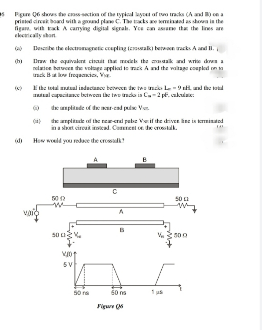
Figure Q6 shows the cross-section of the typical layout of two tracks (A and B) on a
printed circuit board with a ground plane C. The tracks are terminated as shown in the
figure, with track A carrying digital signals. You can assume that the lines are
electrically short.
(a)
Describe the electromagnetic coupling (crosstalk) between tracks A and B.
(b)
Draw the equivalent circuit that models the crosstalk and write down a
relation between the voltage applied to track A and the voltage coupled on to
track B at low frequencies, VNE.
(c)
If the total mutual inductance between the two tracks Lm = 9 nH, and the total
mutual capacitance between the two tracks is Cm = 2 pF, calculate:
(i)
the amplitude of the near-end pulse VNE-
(ii)
the amplitude of the near-end pulse VNE if the driven line is terminated
in a short circuit instead. Comment on the crosstalk.
(d)
How would you reduce the crosstalk?
50 2
50 Ω
B
50 ΩV.
V 3 50 2
Vt)
5 V
50 ns
50 ns
1 μs
Figure Q6
Expert Solution
This question has been solved!
Explore an expertly crafted, step-by-step solution for a thorough understanding of key concepts.

Step by stepSolved in 2 steps with 2 images

Knowledge Booster

Similar questions
arrow_back_ios
arrow_forward_ios