Introductory Circuit Analysis (13th Edition)
13th Edition
ISBN: 9780133923605
Author: Robert L. Boylestad
Publisher: PEARSON
expand_more
expand_more
format_list_bulleted
Concept explainers
Question
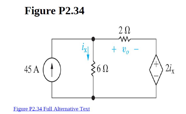
For the circuit shown , find vo and the total power supplied in the circuit.

Transcribed Image Text:Figure P2.34
+ Vo
2ix
45 A
Figure P2.34 Full Alternative Text
Expert Solution
This question has been solved!
Explore an expertly crafted, step-by-step solution for a thorough understanding of key concepts.
This is a popular solution
Trending nowThis is a popular solution!
Step by stepSolved in 2 steps with 1 images

Knowledge Booster
Learn more about
Need a deep-dive on the concept behind this application? Look no further. Learn more about this topic, electrical-engineering and related others by exploring similar questions and additional content below.Similar questions
- note: use article 220 NEC , APPLY STANDARD METHOD 1. A house has a floor area of 1000 ft2, The appliances are an 11 kW stove and a 10 kV, 240 V dryer. Assume that the kW rating of the stove and dryer are equivalent to the kVA rating. - Calculate general lighting load. - Estimate the number of lighting circuits that will be 20A at 120V. - Estimate the number of circuits there will be at 20A at 120V for small appliances and laundry. - Calculate the TOTAL EFFECTIVE LOAD (VA). - Estimate the main circuit breaker and THHW conductors at 75 celsius and neutral for 120/240 volts. Translated with DeepL.com (free version)arrow_forward2. For the network of figure below: a. Find the total conductance and resistance. b. Determine Is and the current through each parallel branch. c. Verify that the source current equals the sum of the parallel branch currents. d. Find the power dissipated by each resistor, and note whether the power delivered is equal to the power dissipated. e. If the resistors are available with wattage ratings of 1/2, 1, 2, and 50 W, what is the minimum wattage rating for each resistor. 0.9 V Gr Rr R₁30 R₂60 R₂ 1.5 Ωarrow_forward3. In Figure, the battery voltage is V=10 volts, and the values of the resistances, in ohms, are 100, 220,and Kas shown. Find: (a) Total resistance seen by the battery, (b) Current measured by the ammeters shown in the figure, (c) Power output of the battery, (d) Power input to each resistor. V 10082 220 Ω 1ΚΩarrow_forward
arrow_back_ios
arrow_forward_ios
Recommended textbooks for you
 Introductory Circuit Analysis (13th Edition)Electrical EngineeringISBN:9780133923605Author:Robert L. BoylestadPublisher:PEARSON
 Delmar's Standard Textbook Of ElectricityElectrical EngineeringISBN:9781337900348Author:Stephen L. HermanPublisher:Cengage Learning
 Programmable Logic ControllersElectrical EngineeringISBN:9780073373843Author:Frank D. PetruzellaPublisher:McGraw-Hill Education
 Fundamentals of Electric CircuitsElectrical EngineeringISBN:9780078028229Author:Charles K Alexander, Matthew SadikuPublisher:McGraw-Hill Education
 Electric Circuits. (11th Edition)Electrical EngineeringISBN:9780134746968Author:James W. Nilsson, Susan RiedelPublisher:PEARSON
 Engineering ElectromagneticsElectrical EngineeringISBN:9780078028151Author:Hayt, William H. (william Hart), Jr, BUCK, John A.Publisher:Mcgraw-hill Education,

Introductory Circuit Analysis (13th Edition)
Electrical Engineering
ISBN:9780133923605
Author:Robert L. Boylestad
Publisher:PEARSON

Delmar's Standard Textbook Of Electricity
Electrical Engineering
ISBN:9781337900348
Author:Stephen L. Herman
Publisher:Cengage Learning

Programmable Logic Controllers
Electrical Engineering
ISBN:9780073373843
Author:Frank D. Petruzella
Publisher:McGraw-Hill Education

Fundamentals of Electric Circuits
Electrical Engineering
ISBN:9780078028229
Author:Charles K Alexander, Matthew Sadiku
Publisher:McGraw-Hill Education

Electric Circuits. (11th Edition)
Electrical Engineering
ISBN:9780134746968
Author:James W. Nilsson, Susan Riedel
Publisher:PEARSON

Engineering Electromagnetics
Electrical Engineering
ISBN:9780078028151
Author:Hayt, William H. (william Hart), Jr, BUCK, John A.
Publisher:Mcgraw-hill Education,