Introductory Circuit Analysis (13th Edition)
13th Edition
ISBN: 9780133923605
Author: Robert L. Boylestad
Publisher: PEARSON
expand_more
expand_more
format_list_bulleted
Question
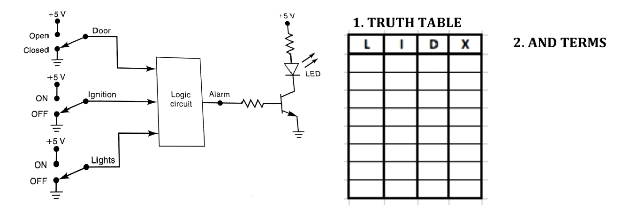
Figure below shows a diagram for an automobile alarm circuit used to detect certain undesirable conditions. The three switches are used to indicate the status of the door by the driver's seat, the ignition, and the headlights. respectively. Design the logic circuit with these three switches as inputs so that the alarm will be activated whenever either of the following conditions exists:
* The headlights are on while the ignition is off.
* The door is open while the ignition is on.
Use only the 5 steps below
1.- Truth table
2.- Terms
3.- SOP
4.- Simplified Expression
5.- Implement the circuit
show the steps of how do it, thanks.

Expert Solution
This question has been solved!
Explore an expertly crafted, step-by-step solution for a thorough understanding of key concepts.
This is a popular solution
Trending nowThis is a popular solution!
Step by stepSolved in 4 steps with 4 images

Knowledge Booster
Learn more about
Need a deep-dive on the concept behind this application? Look no further. Learn more about this topic, electrical-engineering and related others by exploring similar questions and additional content below.Similar questions
- 4. A/An can be described as an imaginary device that exists only in the logic of the computer. a. internal relay b. limit switch C. I/O track d. phototransistor 00nmmended nractice when installing PLCS?arrow_forwardQuestion 5 What is the device address used by the instruction OUT A4, AL?arrow_forward1-What phrase is used when a substitution is permitted for a specific item? 2-The specifications state that all work shall be done... 3-What phrase is used when a substitution is permitted for a specific item? 4-What is the purpose of an electrical symbol? 5. Where are notations found?arrow_forward
- PWM is the method that; 1. Sends an encrypted message. 2. Brakes a motor. 3. Creates an equivalent analog effect from digital pulses. 4. Creates an equivalent digital effect from analog pulses. 5. Runs a motor in forward and backward.arrow_forwardConclusion From your life experiences, list 3-5 examples of products that you have used that contain combinational logic. Throughout this activity we used switches for the circuit inputs and a probe for the circuit outputs. Though this works fine for testing purposes, it is not practical for real-world applications of combinational logic circuits. List three input and three output devices that would be used with real world applications of combinational logic. Going Further – Optional As mentioned in the purpose section of this activity, combinational logic circuits can be implemented with a variety of different logic gates. One such gate is called the NAND gates (see below). Functionally, the NAND gate is an AND gate with its output inverted. The picture added goes here Using what you know about the AND gate and Inverter gates, complete the truth table for the NAND gate. A B C 0 0 0 1 1 0 1 1…arrow_forwardBook used is Digital Logic with Verilog Design by Brown & Vranesic. Study the counting circuit diagram below and answer the following questions: a. Based on the circuit drawing, is the Clock Positive-Edge Triggered or Negative-Edge Triggered? b. How was this determination made? c. What are the minimum and maximum valkues of the circuit? Explain. d. There are 3 grayed out boxes we refer to this symbolic use as _____________. Why are these used in circuit design?arrow_forward
arrow_back_ios
arrow_forward_ios
Recommended textbooks for you
 Introductory Circuit Analysis (13th Edition)Electrical EngineeringISBN:9780133923605Author:Robert L. BoylestadPublisher:PEARSON
 Delmar's Standard Textbook Of ElectricityElectrical EngineeringISBN:9781337900348Author:Stephen L. HermanPublisher:Cengage Learning
 Programmable Logic ControllersElectrical EngineeringISBN:9780073373843Author:Frank D. PetruzellaPublisher:McGraw-Hill Education
 Fundamentals of Electric CircuitsElectrical EngineeringISBN:9780078028229Author:Charles K Alexander, Matthew SadikuPublisher:McGraw-Hill Education
 Electric Circuits. (11th Edition)Electrical EngineeringISBN:9780134746968Author:James W. Nilsson, Susan RiedelPublisher:PEARSON
 Engineering ElectromagneticsElectrical EngineeringISBN:9780078028151Author:Hayt, William H. (william Hart), Jr, BUCK, John A.Publisher:Mcgraw-hill Education,

Introductory Circuit Analysis (13th Edition)
Electrical Engineering
ISBN:9780133923605
Author:Robert L. Boylestad
Publisher:PEARSON

Delmar's Standard Textbook Of Electricity
Electrical Engineering
ISBN:9781337900348
Author:Stephen L. Herman
Publisher:Cengage Learning

Programmable Logic Controllers
Electrical Engineering
ISBN:9780073373843
Author:Frank D. Petruzella
Publisher:McGraw-Hill Education

Fundamentals of Electric Circuits
Electrical Engineering
ISBN:9780078028229
Author:Charles K Alexander, Matthew Sadiku
Publisher:McGraw-Hill Education

Electric Circuits. (11th Edition)
Electrical Engineering
ISBN:9780134746968
Author:James W. Nilsson, Susan Riedel
Publisher:PEARSON

Engineering Electromagnetics
Electrical Engineering
ISBN:9780078028151
Author:Hayt, William H. (william Hart), Jr, BUCK, John A.
Publisher:Mcgraw-hill Education,