Introductory Circuit Analysis (13th Edition)
13th Edition
ISBN: 9780133923605
Author: Robert L. Boylestad
Publisher: PEARSON
expand_more
expand_more
format_list_bulleted
Question

Transcribed Image Text:Note:
The plots using Matlab should include all important aspects related to the analysis. Specifically,
the plots should show:
1. The uncompensated system.
2. The response of the uncompensated system.
3. The compensated system.
4. The response of the compensated system.
These elements ensure a comprehensive representation of both the systems and their behaviors
before and after compensation.

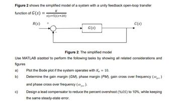
Transcribed Image Text:Figure 2 shows the simplified model of a system with a unity feedback open-loop transfer
K
function of G(s).
s(s+5)(s+20)
R(s)
+
G(s)
C(s)
Figure 2: The simplified model
Use MATLAB sisotool to perform the following tasks by showing all related considerations and
figures
a)
b)
c)
Plot the Bode plot if the system operates with K₁ = 10.
Determine the gain margin (GM), phase margin (PM), gain cross over frequency (@gc.)
and phase cross over frequency (p).
Design a lead compensator to reduce the percent overshoot (%OS) to 10%, while keeping
the same steady-state error.
SAVE
AI-Generated Solution
info
AI-generated content may present inaccurate or offensive content that does not represent bartleby’s views.
Unlock instant AI solutions
Tap the button
to generate a solution
to generate a solution
Click the button to generate
a solution
a solution
Knowledge Booster
Similar questions
- Significance of transient behaviour in control systems. Could an example with temperature control for a human occupied building be provided?arrow_forwardDerive the expression for Zinarrow_forwardDiscuss the importance of power delivery and voltage regulation on a motherboard. How do voltage regulators and capacitors ensure stable power to components?arrow_forward
Recommended textbooks for you
 Introductory Circuit Analysis (13th Edition)Electrical EngineeringISBN:9780133923605Author:Robert L. BoylestadPublisher:PEARSON
 Delmar's Standard Textbook Of ElectricityElectrical EngineeringISBN:9781337900348Author:Stephen L. HermanPublisher:Cengage Learning
 Programmable Logic ControllersElectrical EngineeringISBN:9780073373843Author:Frank D. PetruzellaPublisher:McGraw-Hill Education
 Fundamentals of Electric CircuitsElectrical EngineeringISBN:9780078028229Author:Charles K Alexander, Matthew SadikuPublisher:McGraw-Hill Education
 Electric Circuits. (11th Edition)Electrical EngineeringISBN:9780134746968Author:James W. Nilsson, Susan RiedelPublisher:PEARSON
 Engineering ElectromagneticsElectrical EngineeringISBN:9780078028151Author:Hayt, William H. (william Hart), Jr, BUCK, John A.Publisher:Mcgraw-hill Education,

Introductory Circuit Analysis (13th Edition)
Electrical Engineering
ISBN:9780133923605
Author:Robert L. Boylestad
Publisher:PEARSON

Delmar's Standard Textbook Of Electricity
Electrical Engineering
ISBN:9781337900348
Author:Stephen L. Herman
Publisher:Cengage Learning

Programmable Logic Controllers
Electrical Engineering
ISBN:9780073373843
Author:Frank D. Petruzella
Publisher:McGraw-Hill Education

Fundamentals of Electric Circuits
Electrical Engineering
ISBN:9780078028229
Author:Charles K Alexander, Matthew Sadiku
Publisher:McGraw-Hill Education

Electric Circuits. (11th Edition)
Electrical Engineering
ISBN:9780134746968
Author:James W. Nilsson, Susan Riedel
Publisher:PEARSON

Engineering Electromagnetics
Electrical Engineering
ISBN:9780078028151
Author:Hayt, William H. (william Hart), Jr, BUCK, John A.
Publisher:Mcgraw-hill Education,