Database System Concepts
7th Edition
ISBN: 9780078022159
Author: Abraham Silberschatz Professor, Henry F. Korth, S. Sudarshan
Publisher: McGraw-Hill Education
expand_more
expand_more
format_list_bulleted
Question
please answer within 30 minutes.

Transcribed Image Text:(c)
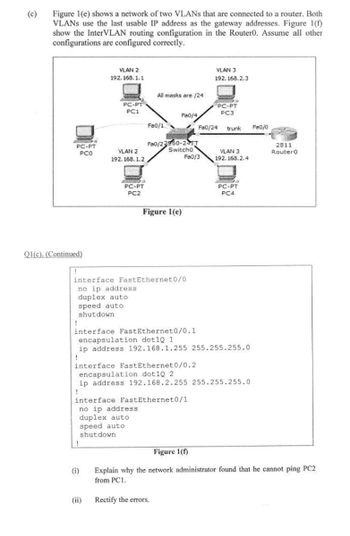
Figure 1(e) shows a network of two VLANs that are connected to a router. Both
VLANs use the last usable IP address as the gateway addresses. Figure 1(f)
show the InterVLAN routing configuration in the Router0. Assume all other
configurations are configured correctly.
VLAN 2
VLAN 3
192.168.2.3
192.168.1.1
weeker
All masks are /24
PC-PT
WAS
SOU
PC-PT
PC3
PC1
Fa0/4
Fa0/1
Fa0/24 trunk
Fa0/22950-24TT
Switcho
VLAN 2
192.168.1.2
Fa0/3
ANG &
PC-PT
PC2
d
PC-PT
PCO
Q1(c). (Continued)
VLAN 3
192.168.2.4
POMO
PC-PT
PC4
(i)
(ii)
Fa0/0
Figure 1(e)
interface FastEthernet0/0
no ip address
duplex auto
speed auto
shutdown
!
interface FastEthernet0/0.1
encapsulation dot1Q 1
ip address 192.168.1.255 255.255.255.0
interface FastEthernet0/0.2
encapsulation dot1Q 2
ip address 192.168.2.255 255.255.255.0
!
interface FastEthernet0/1
no ip address.
duplex auto
speed auto
shutdown
Figure 1(f)
Explain why the network administrator found that he cannot ping PC2
from PC1.
Rectify the errors.
2811
RouterO

Transcribed Image Text:(c)
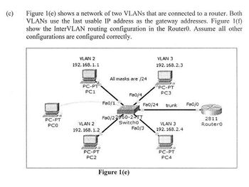
Figure 1(e) shows a network of two VLANs that are connected to a router. Both
VLANS use the last usable IP address as the gateway addresses. Figure 1(f)
show the InterVLAN routing configuration in the Router0. Assume all other
configurations are configured correctly.
VLAN 2
VLAN 3
192.168.2.3
192.168.1.1
All masks are /24
PC-PT
PC-PT
PC1
PC3
Fa0/4
Fa0/1
Fa0/24 trunk
Fa0/22950-2-TT
Switch0
VLAN 2
192.168.1.2
Fa0/3
PC-PT
PC2
PC-PT
PCO
Figure 1(e)
VLAN 3
192.168.2.4
PC-PT
PC4
Fa0/0
2811
Router0
Expert Solution
This question has been solved!
Explore an expertly crafted, step-by-step solution for a thorough understanding of key concepts.
Step by stepSolved in 2 steps

Knowledge Booster
Learn more about
Need a deep-dive on the concept behind this application? Look no further. Learn more about this topic, computer-science and related others by exploring similar questions and additional content below.Similar questions
Recommended textbooks for you
 Database System ConceptsComputer ScienceISBN:9780078022159Author:Abraham Silberschatz Professor, Henry F. Korth, S. SudarshanPublisher:McGraw-Hill Education
 Starting Out with Python (4th Edition)Computer ScienceISBN:9780134444321Author:Tony GaddisPublisher:PEARSON
 Digital Fundamentals (11th Edition)Computer ScienceISBN:9780132737968Author:Thomas L. FloydPublisher:PEARSON
 C How to Program (8th Edition)Computer ScienceISBN:9780133976892Author:Paul J. Deitel, Harvey DeitelPublisher:PEARSON
 Database Systems: Design, Implementation, & Manag...Computer ScienceISBN:9781337627900Author:Carlos Coronel, Steven MorrisPublisher:Cengage Learning
 Programmable Logic ControllersComputer ScienceISBN:9780073373843Author:Frank D. PetruzellaPublisher:McGraw-Hill Education

Database System Concepts
Computer Science
ISBN:9780078022159
Author:Abraham Silberschatz Professor, Henry F. Korth, S. Sudarshan
Publisher:McGraw-Hill Education

Starting Out with Python (4th Edition)
Computer Science
ISBN:9780134444321
Author:Tony Gaddis
Publisher:PEARSON

Digital Fundamentals (11th Edition)
Computer Science
ISBN:9780132737968
Author:Thomas L. Floyd
Publisher:PEARSON

C How to Program (8th Edition)
Computer Science
ISBN:9780133976892
Author:Paul J. Deitel, Harvey Deitel
Publisher:PEARSON

Database Systems: Design, Implementation, & Manag...
Computer Science
ISBN:9781337627900
Author:Carlos Coronel, Steven Morris
Publisher:Cengage Learning

Programmable Logic Controllers
Computer Science
ISBN:9780073373843
Author:Frank D. Petruzella
Publisher:McGraw-Hill Education