
Power System Analysis and Design (MindTap Course List)
6th Edition
ISBN: 9781305632134
Author: J. Duncan Glover, Thomas Overbye, Mulukutla S. Sarma
Publisher: Cengage Learning
expand_more
expand_more
format_list_bulleted
Related questions
Question
Find the transfer function of the following closed loop
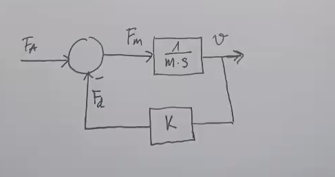

Transcribed Image Text:FA
Fm
MS
ひ
K
Expert Solution
This question has been solved!
Explore an expertly crafted, step-by-step solution for a thorough understanding of key concepts.

Step by stepSolved in 2 steps

Knowledge Booster

Similar questions
- Ac - 100 VrmsR1 - 1kR2 - 500Rload - 1kCapacitor - 2uF Q1. How much is the capacitor voltage lagging from the AC sourcearrow_forwardZp Np N₁ Z₁ solve for Zparrow_forwardQ.4Determine the current flowing in the capacitor(-j25ohm) and its direction as shown in Figure below. Assume the voltage source to have negligible impedance.arrow_forward
- Draw the waveform of voltage and current under the following conditions: A current which lags the voltage by 60°. A current which leads the voltage by 60°. A current which is in phase with the voltagearrow_forwardHow did they get these equation explain simply?arrow_forwardplz solve this part step by steparrow_forward
- Having a hard time solving and graphing, can you help me please?arrow_forwardA certain impedance is given by 1012° N. Does the current lead or lag the voltage, and by how many degrees? Fill in the blanks. The current the voltage byarrow_forwardThe rms value of v(t)=Vmaxcos(t+) is given by a. Vmax b. Vmax/2 c. 2Vmax d. 2Vmaxarrow_forward
- 41. Two ac sources feed a common variable resistive load as shown in figure. Under the maximum power transfer condition, the power absorbed by the load resistance R, is lall 6 2 j8 2 6 2 11020 ( 0706 O9020° (a) 2200 W (b) 1250 W (c) 1000 W (d) 625 Warrow_forward3- Please I want answer of this Electrical Principles question. Thanksarrow_forwardin V1 R2 100k SINE(0 10 100) R1 100k D1 D V2 0 out D D2 V3 0 DC offset[V]: 0 Amplitude[V]: 10 Freq[Hz]: 100 T delay[s]: Theta[1/s]: Phi[deg]: Ncycles: anter 2019-2220 Figure 3-5 Clipper Circuit for LTSPICE Simulation C4. To specify the type of simulation, select "Simulate>>Edit Simulation Cmd" from the menu. Choose "Transient" and enter 30m for Stop time, 0 for Time to start saving data, and 1m for Maximum Timestep. Click OK. C5. Click Run to start the analysis. C6. Place two voltage probes (voltage probes appear when placed on a wire during simulation), one at the input side (at the top of V1) and another at the output side (at the top of D2) of the circuit. What difference do you observe between the input and the output waveforms?arrow_forward
arrow_back_ios
SEE MORE QUESTIONS
arrow_forward_ios
Recommended textbooks for you
- Power System Analysis and Design (MindTap Course ...Electrical EngineeringISBN:9781305632134Author:J. Duncan Glover, Thomas Overbye, Mulukutla S. SarmaPublisher:Cengage Learning
Power System Analysis and Design (MindTap Course ...
Electrical Engineering
ISBN:9781305632134
Author:J. Duncan Glover, Thomas Overbye, Mulukutla S. Sarma
Publisher:Cengage Learning