
Introductory Circuit Analysis (13th Edition)
13th Edition
ISBN: 9780133923605
Author: Robert L. Boylestad
Publisher: PEARSON
expand_more
expand_more
format_list_bulleted
Related questions
Question
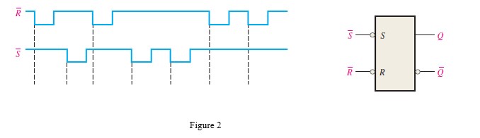
Explain the difference between D-Latch and D flip flop with the help of diagram? If the ̅s and ̅R waveforms in Figure 2 are applied to the inputs of the latch as shown, determine the waveform that will be observed on the Q output. Assume that Q is initially LOW
Kindly Handwritten

Transcribed Image Text:R R
Figure 2
Expert Solution
This question has been solved!
Explore an expertly crafted, step-by-step solution for a thorough understanding of key concepts.

This is a popular solution

Trending nowThis is a popular solution!

Step by stepSolved in 2 steps with 2 images

Knowledge Booster


Learn more about
Need a deep-dive on the concept behind this application? Look no further. Learn more about this topic, electrical-engineering and related others by exploring similar questions and additional content below.Similar questions
- show the waveforms for each flip-flop output with respect For the ring counter in Figure to the clock. Assume that FF0 is initially SET and that the rest are RESET. Show at least ten clock pulses. D D. FFO FF1 FF2 FF3 FF4 FF5 FF6 FF7 FF8 FP9 CLKarrow_forwardWrite the next-state equations for the flip-flops and the output equation. (b) Construct the transition and output tables. (c) Construct the transition graph. (d) Give a one-sentence description of when the circuit produces an output of 1. Q2 D2 Q1 T1 CLK Figure 4arrow_forwardUsing 4 J-k flip flops explain how a counter can be built with the aid of a diagramarrow_forward
- What is NOR gate R-S flip flop?arrow_forwardFigure 2.1 shows the Asynchronous J-K flip flop and it truth table. Draw an output waveform, Q by drag and drop the correct waveform. Q is initially LOW. Clock Preset Clear Input J Input K Output J CLK K PRESET a Q CLEAR PRESET 1 0 CLEAR 1 1 0 0 Figure 2.1 FF response Clocked operation" Q1 (regardless of CLK) Q=0 (regardless of CLK) Not used 0 *Q will respond to J, K, and CLKarrow_forwardcheck the image for questionarrow_forward
arrow_back_ios
arrow_forward_ios
Recommended textbooks for you
- Introductory Circuit Analysis (13th Edition)Electrical EngineeringISBN:9780133923605Author:Robert L. BoylestadPublisher:PEARSON
 Delmar's Standard Textbook Of ElectricityElectrical EngineeringISBN:9781337900348Author:Stephen L. HermanPublisher:Cengage Learning
 Programmable Logic ControllersElectrical EngineeringISBN:9780073373843Author:Frank D. PetruzellaPublisher:McGraw-Hill Education
  Fundamentals of Electric CircuitsElectrical EngineeringISBN:9780078028229Author:Charles K Alexander, Matthew SadikuPublisher:McGraw-Hill Education
 Electric Circuits. (11th Edition)Electrical EngineeringISBN:9780134746968Author:James W. Nilsson, Susan RiedelPublisher:PEARSON
 Engineering ElectromagneticsElectrical EngineeringISBN:9780078028151Author:Hayt, William H. (william Hart), Jr, BUCK, John A.Publisher:Mcgraw-hill Education,
Introductory Circuit Analysis (13th Edition)
Electrical Engineering
ISBN:9780133923605
Author:Robert L. Boylestad
Publisher:PEARSON
Delmar's Standard Textbook Of Electricity
Electrical Engineering
ISBN:9781337900348
Author:Stephen L. Herman
Publisher:Cengage Learning
Programmable Logic Controllers
Electrical Engineering
ISBN:9780073373843
Author:Frank D. Petruzella
Publisher:McGraw-Hill Education
Fundamentals of Electric Circuits
Electrical Engineering
ISBN:9780078028229
Author:Charles K Alexander, Matthew Sadiku
Publisher:McGraw-Hill Education
Electric Circuits. (11th Edition)
Electrical Engineering
ISBN:9780134746968
Author:James W. Nilsson, Susan Riedel
Publisher:PEARSON
Engineering Electromagnetics
Electrical Engineering
ISBN:9780078028151
Author:Hayt, William H. (william Hart), Jr, BUCK, John A.
Publisher:Mcgraw-hill Education,