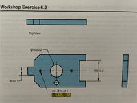
Exercise 6.2. Label the drawing that is attached.
1. Create datum plane A on the right hand face in the side view.
2. Create datum plane B on the bottom surface in the front view.
3. Create datum plane C on the top surface of the 40 mm tab.
4. Create datum center plane D in the center of the tab.
5. Create datum center plane E in the center of the 100 mm slot.
6. Create datum plane F on the left side of the slot.
7. Create a partial datum plane G on the top of the part in the front view. The length is 120 mm from the right side.
8. Create datum H, axis and two planes, through the two 10 mm holes.
9. Create datum axis J from the 60 mm hole.
10. Datum features can be placed into two categories - datum features of size and datum features without size. Place an "X" next to all the datum features of size.

Trending nowThis is a popular solution!
Step by stepSolved in 2 steps with 1 images

 Elements Of ElectromagneticsMechanical EngineeringISBN:9780190698614Author:Sadiku, Matthew N. O.Publisher:Oxford University Press
 Mechanics of Materials (10th Edition)Mechanical EngineeringISBN:9780134319650Author:Russell C. HibbelerPublisher:PEARSON
 Thermodynamics: An Engineering ApproachMechanical EngineeringISBN:9781259822674Author:Yunus A. Cengel Dr., Michael A. BolesPublisher:McGraw-Hill Education
 Control Systems EngineeringMechanical EngineeringISBN:9781118170519Author:Norman S. NisePublisher:WILEY
 Mechanics of Materials (MindTap Course List)Mechanical EngineeringISBN:9781337093347Author:Barry J. Goodno, James M. GerePublisher:Cengage Learning
 Engineering Mechanics: StaticsMechanical EngineeringISBN:9781118807330Author:James L. Meriam, L. G. Kraige, J. N. BoltonPublisher:WILEY


