Related questions
Concept explainers
Question
(II) Design a “voltage divider” (see Example 19–3) that
would provide one-fifth (0.20) of the battery voltage across R2
Fig. 19–6. What is the ratio R1/R2
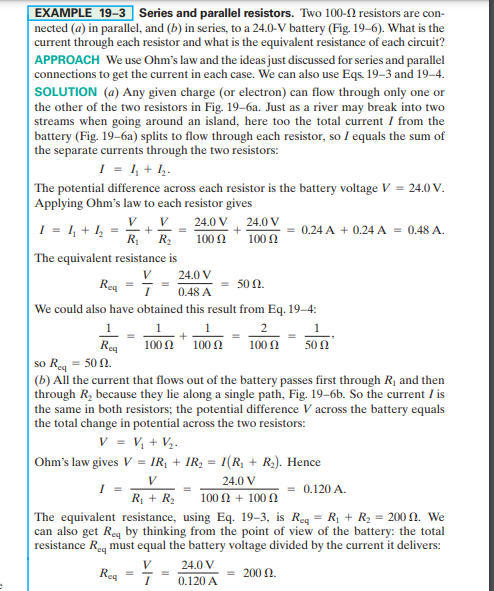

Transcribed Image Text:EXAMPLE 19-3 Series and parallel resistors. Two 100-0 resistors are con-
nected (a) in parallel, and (b) in series, to a 24.0-V battery (Fig. 19–6). What is the
current through each resistor and what is the equivalent resistance of each circuit?
APPROACH We use Ohm's law and the ideas just discussed for series and parallel
connections to get the current in each case. We can also use Eqs. 19–3 and 19-4.
SOLUTION (a) Any given charge (or electron) can flow through only one or
the other of the two resistors in Fig. 19-6a. Just as a river may break into two
streams when going around an island, here too the total current I from the
battery (Fig. 19–6a) splits to flow through each resistor, so I equals the sum of
the separate currents through the two resistors:
I = 1, + 4.
|The potential difference across each resistor is the battery voltage V = 24.0 V.
Applying Ohm's law to each resistor gives
V
V
24.0 V, 24.0 V
I = 1, + I,
R
0.24 A + 0.24 A = 0.48 A.
R2
100 Ω
100 N
|The equivalent resistance is
24.0 V
Reg
50 Ω.
0.48 A
We could also have obtained this result from Eq. 19–4:
1
1
2
1
Rea
100Ω, 100 η
50 N
100 Ω
so Re = 50 2.
(b) All the current that flows out of the battery passes first through R, and then
through R, because they lie along a single path, Fig. 19–6b. So the current I is
the same in both resistors; the potential difference V across the battery equals
the total change in potential across the two resistors:
V = V, + V½.
Ohm's law gives V = IR, + IR, = I(R, + R.). Hence
V
24.0 V
= 0.120 A.
R + R2
100 Ω + 100 Ω
The equivalent resistance, using Eq. 19–3, is Reg = R1 + R2 = 200 0. We
can also get Req by thinking from the point of view of the battery: the total
resistance Reg must equal the battery voltage divided by the current it delivers:
V
24.0 V
Reg
0.120 A
200 Ω.

Transcribed Image Text:V = 24.0 V
R1
R2
ww
(a)
V = 24.0 V
ww
ww
R1
R2
(b)
FIGURE 19-6 Example 19–3.
Expert Solution
This question has been solved!
Explore an expertly crafted, step-by-step solution for a thorough understanding of key concepts.

This is a popular solution

Trending nowThis is a popular solution!

Step by stepSolved in 3 steps with 1 images

Knowledge Booster


Learn more about
Need a deep-dive on the concept behind this application? Look no further. Learn more about this topic, advanced-physics and related others by exploring similar questions and additional content below.Similar questions
- Two separate capacitors, C1 and C2 C1 = 36 micro-Coulomb on 3 micro-Farad C2 = 72 uC on X uF, X = 3.5 , if zero X =2 C2 had a gap of 0.2m maintained by a compressed plastic spring inside the gap, the natural spring length was 0.5m, the compressed spring length was 0.2 m. Spring constant = 8,000 micro-Newton/ meter Action: Connected the two capacitors in parallel Part A Find Q2-new, C2-new, new gap Part B Find the initial total energy, the final total energyarrow_forwardSuppose you are given several capacitors whose capacitances are within the range 12 to 50 nF.You connect all the capacitors in series and let your three partners measure the equivalent capacitance. Three different measurements have been obtained: 8, 44 and 102 nF. Which ofthese three you would assume to be correct?arrow_forward(d) Two capacitors are in series across a 60V source. If one is a 1 µF capacitor with a 15 V across it, what is the capacitance of the other capacitor?arrow_forward
- In computing power, it was stated that the battery voltage must be measured "under load". What happens to the voltage when the battery is under load? Why does this happen?arrow_forward(III) (a) Determine the currents I₁, 12, and I3 in Fig. 19–61. Assume the internal resistance of each battery is r = 1.0. (b) What is the terminal voltage of the 6.0-V battery? r WITH 12.0 V 22 Ω 12 Ω 28 Ω FIGURE 19-61 Problems 34 and 35. 12.0 V 112 r 16 Ω |_ 6.0 V 13arrow_forward
arrow_back_ios
arrow_forward_ios