Power System Analysis and Design (MindTap Course List)
6th Edition
ISBN: 9781305632134
Author: J. Duncan Glover, Thomas Overbye, Mulukutla S. Sarma
Publisher: Cengage Learning
expand_more
expand_more
format_list_bulleted
Question

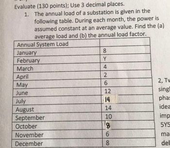
Transcribed Image Text:Evaluate (130 points); Use 3 decimal places.
1. The annual load of a substation is given in the
following table. During each month, the power is
assumed constant at an average value. Find the (a)
average load and (b) the annual load factor.
Annual System Load
January
February
March
8
Y
4
April
May
26
2
6
2, Tv
June
12
sing
July
14
phas
August
14
idea
September
10
imp
October
8
5Y5
November
December
68
6
ma
del
Expert Solution
This question has been solved!
Explore an expertly crafted, step-by-step solution for a thorough understanding of key concepts.
Step by stepSolved in 1 steps

Knowledge Booster
Similar questions
- High voltage engineering subjectarrow_forwardThe peak load on a 50 MW power station is 39 MW. It supplies power through for transformers whose connected loads are 17, 12,9 and 10 MW. The maximum demands on these transformers are 15, 10, 8 and 9 MW respectively. The annual load factor is 50% and the plant is operating for 65% of the period in a year. 102. The average load on the station is (A) 50000 kW (C) 39000 kW (B) 19500 kW (D) 48000 kW. 103. The energy supplied per year is (A) 438 x 106 kWh (C) 170.82 x 10⁶ kWh (B) 341.64 x 10⁶ kWh (D) 420.48 x 10⁶ kWh.arrow_forwardFind the following : 1.Ripple Voltage (vpp) 2. Zero-to peak ripple(Vop) 3.secondary winding of the transformer high line and low linearrow_forward
- A 10 MVA three phase load is to be served by a three phase transformer at aline voltage of 13.8 kV. The supply side voltage(line-line) is 138 kV. Varioussingle phase transformers are available in the warehouse but all havewindings with voltage ratings under 100 kV and current ratings under 250 A.Is it possible to serve the load using only three single phase transformers? Ifso, specify the three phase connections and the low and high voltage ratingsof the single phase transformers.arrow_forward1. A single-phase power system as shown in Figure 1 consists of a 240 V, 60 Hz generator supplying a load, Zod = 8 + j6 Q through a transmission line of impedance, Zne = 0.08 + j0.14 Q. Answer the following questions: (1) transformer, T; and T2. Determine the voltage at the load and transmission line losses without the (ii) Determine the voltage at the load and transmission line losses with the transformer, T, and T2. T1 T2 1:10 10:1 IG Zaine Zioad source Figure 1arrow_forwardA generator connected through 5 cycle CB to a transformer is rated 8000 kVA with the reactances of X"= 10 %, X₁ = 16% and Xa = 100 %. It is operating at no load and rated voltage when 3 phase short circuit occurs between breaker and transformer. Find: i) sustained short circuit in breaker ii) the initial symmetrical rms current in breaker iii) maximum possible d.c. component of short circuit in breaker iv) the momentary current rating of the breaker v) current to be interrupted by breaker vi) the interrupting kVAarrow_forward
- Assume that there are two primary feeders supplied by a transformer T1. One of the feeders supplies an industrial load which occurs primarily between 8 AM, and 11 P.M. with a peak of 2400 kw at 5 P.M. The other one feeds residential loads which occur mainly betwveen 6 A.M. and 12 P.M., with a peak of 2000 kW at 9 P.M. The diversity factor of the load connected to transformer T1 is 1.3: The maximum diversified demand of the load connected to transformer T1.arrow_forwardSolution in typing pleasearrow_forwardIn a PWM, how do we calculate duty cycle?arrow_forward
- In the system shown in Figure 1, the transformers are connected star-star with both star points grounded and the generator is connected in star with its star points grounded. The per unit impedances of each element on a 40 MVA base are given in Table 1 and the voltage levels are given in Table 2. Z [p.u.] 0 2 tööt Generator 0.01 +j0.08 p.u. L Figure 1: A section of the distribution system Transformer T1 Line V BASE [KV] 0.04 + j 0.03 + j 0.15000000000000002 0.06000000000000000 Generator Table 1: Sequence impedances (p.u. on 40 MVA base) 3 T2 181. Line 3 10 Table 2: Voltage bases (kV) Load 1 Transformer T2 Load Current A load current of 11.316 kA is flowing with a lagging power factor of 90 %. Convert this to a current vector in per-unit. IL = 0.04 + j 0.06000000000000000arrow_forward4.a. A demountable stud bushing on high-voltage leads eliminates the need fora. an oil stop.b. a gasket.c. a terminal lug. 4.a. A power transformer with standard insulation class of 69 kv will withstand an rms test voltage ofA. 140 kv.B. 440 kv.c. 69kv.arrow_forwardConsider the three single-phase two-winding transformers shown in Figure 3.37. The high-voltage windings are connected in Y. (a) For the low-voltage side, connect the windings in , place the polarity marks, and label the terminals a, b, and c in accordance with the American standard. (b) Relabel the terminals a, b, and c such that VAN is 90 out of phase with Va for positive sequence.arrow_forward
arrow_back_ios
SEE MORE QUESTIONS
arrow_forward_ios
Recommended textbooks for you
 Power System Analysis and Design (MindTap Course ...Electrical EngineeringISBN:9781305632134Author:J. Duncan Glover, Thomas Overbye, Mulukutla S. SarmaPublisher:Cengage Learning

Power System Analysis and Design (MindTap Course ...
Electrical Engineering
ISBN:9781305632134
Author:J. Duncan Glover, Thomas Overbye, Mulukutla S. Sarma
Publisher:Cengage Learning