Introductory Circuit Analysis (13th Edition)
13th Edition
ISBN: 9780133923605
Author: Robert L. Boylestad
Publisher: PEARSON
expand_more
expand_more
format_list_bulleted
Question
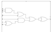
Write the truth table and expression for the following

Transcribed Image Text:E.
Expert Solution
This question has been solved!
Explore an expertly crafted, step-by-step solution for a thorough understanding of key concepts.
Step by stepSolved in 2 steps with 1 images

Knowledge Booster
Learn more about
Need a deep-dive on the concept behind this application? Look no further. Learn more about this topic, electrical-engineering and related others by exploring similar questions and additional content below.Similar questions
- A car seat belt interlock requires that the car should only start if the driver's seat belt is fastened and either the front passenger seat is unoccupied or the front passenger seat is occupied and the passenger seat belt is fastened. i) Obtain the truth table of the system ii) Obtain the SOP Boolean expression for the system. iii) Use a Karnaugh map to simplify the SOP Boolean expression iv) Implement the system using AND, NOT and OR logic gates.arrow_forwardConstruct the truth table for the Full Adder and show the standard Sop expressions for theoutputs. Use the Boolean algebra to simplify the output expressions and draw the simplifiedcircuit.arrow_forwarduse the picture provided, where we filled out the truth table for the 2-bit adder. We also wrote out a logical expression for the s0 bit, following a sum of products approach. For the s1 bit of the new circuit, follow the same procedure and write out the logical expression.arrow_forward
- Derive the truth table for a majority function which is generated in a combinational circuit when the output is one less than the input if the input has more 1s than 0s. The output is one greater than the input, otherwise. Design a combination circuit using ROM. Use ABC as your input variables and XYZ as your output variables. How many OR gates are need to design the circuit? Which of the output lines are connected to the logic gate for output X? Which of the output lines are connected to the logic gate for output Y? Which of the output lines are connected to the logic gate for output Z?arrow_forwardFile name: Mystery.asm In this exercise, you will be creating a 4-variable K-map to minimize the logic for the truth table below. From the minimized K- map, please write the HDL code using standard, built-in chips, such as (And, Not, Or, XOr, Mux, DMux). BCD Out 00000 OO100 0100 0 O1100 B0000 30011 1011 : 1011 B110 0arrow_forwardFor the following question, you need to create a truth table, write the Boolean expression for each output based on the truth table, use K-map to simplify the expression if possible, and draw the logic diagram using AND, OR, NOT gate only. 1. Design a 3-bit shifter. a. A0, A1, A2, and S as inputs b. If S=0, then shift one bit to the left and add 0 to the last bit c. If S=1, then shift one bit to the right and add 0 to the first bit d. Y0, Y1, and Y2 as outputsarrow_forward
- 4. (a) Develop a truth table of the following flipflop: PRE R CLR 4(b) How to convert a JK flip flop into T flipflop? Explain an application of a JK flipflop.arrow_forwardsingle perceptron of a neural network.Q) The logical NOT is a little trickier than AND or OR, but can be done. In this case, there is only one Boolean input. What would the weight and threshold be for this perceptron to recognize the logical NOT operatorarrow_forwardQuestion 1 1.1 Discuss the half-adder, show the following: truth-table, minimal logic expression fo output sum and carry out and logic circuit. Add a caption..arrow_forward
arrow_back_ios
SEE MORE QUESTIONS
arrow_forward_ios
Recommended textbooks for you
 Introductory Circuit Analysis (13th Edition)Electrical EngineeringISBN:9780133923605Author:Robert L. BoylestadPublisher:PEARSON
 Delmar's Standard Textbook Of ElectricityElectrical EngineeringISBN:9781337900348Author:Stephen L. HermanPublisher:Cengage Learning
 Programmable Logic ControllersElectrical EngineeringISBN:9780073373843Author:Frank D. PetruzellaPublisher:McGraw-Hill Education
 Fundamentals of Electric CircuitsElectrical EngineeringISBN:9780078028229Author:Charles K Alexander, Matthew SadikuPublisher:McGraw-Hill Education
 Electric Circuits. (11th Edition)Electrical EngineeringISBN:9780134746968Author:James W. Nilsson, Susan RiedelPublisher:PEARSON
 Engineering ElectromagneticsElectrical EngineeringISBN:9780078028151Author:Hayt, William H. (william Hart), Jr, BUCK, John A.Publisher:Mcgraw-hill Education,

Introductory Circuit Analysis (13th Edition)
Electrical Engineering
ISBN:9780133923605
Author:Robert L. Boylestad
Publisher:PEARSON

Delmar's Standard Textbook Of Electricity
Electrical Engineering
ISBN:9781337900348
Author:Stephen L. Herman
Publisher:Cengage Learning

Programmable Logic Controllers
Electrical Engineering
ISBN:9780073373843
Author:Frank D. Petruzella
Publisher:McGraw-Hill Education

Fundamentals of Electric Circuits
Electrical Engineering
ISBN:9780078028229
Author:Charles K Alexander, Matthew Sadiku
Publisher:McGraw-Hill Education

Electric Circuits. (11th Edition)
Electrical Engineering
ISBN:9780134746968
Author:James W. Nilsson, Susan Riedel
Publisher:PEARSON

Engineering Electromagnetics
Electrical Engineering
ISBN:9780078028151
Author:Hayt, William H. (william Hart), Jr, BUCK, John A.
Publisher:Mcgraw-hill Education,