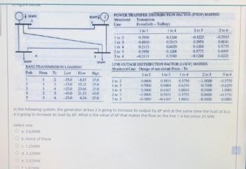
infrigore below. 30 MW 30 MAW BASE TRANSMISSION LOADING Path 2 3 4 5 Select one: O a. 3.62MW From To Low Flow High -35.0 -8.87 35.0 -35.0 15.21 35.0 -25.0 23.66 25.0 -40.0 21.13 40.0 -25.0 6.34 25.0 1 1 O c. 1.25MW 1 2 3 b. None of these d. 2.32MW e. 3.92MW 3.82MW 2 3 4 30 MW 3 4 3 30 MW POWER TRANSFER DISTRIBUTION FACTOR (PIDF) MATRIX Monitored Transaction Line 1 to 2 1 to 3 1 to 4 2 to 3 3 to 4 From(Sell)-To(Buy) 1 to 3 0.2958 0.4930 0.2113 0.2958 -0.2113 1 to 2 1 to 3 1 to 4 2 to 3 3 to 4 1 to 4 0.1268 0.2113 0,6620 0.1268 0.3380 LINE OUTAGE DISTRIBUTION FACTOR (LODF) MATRIX Monitored Line Outage of one circuit From-To 1 to 3 1 to 4 1 to 2 0.0000 0.7000 0.3000 -1.0000 -0.3000 0.3750 0.6250 2 to 3 -0.4225 0.2958 0.1268 0.5775 -0.1268 0.5833 0.0000 0.4167 0.0000 0.5833 0.3750 -0.4167 1.0000 In the following system, the generator at bus 2 is going to increase its output by AP and at the same time the load at bus 4 is going to increase its load by AP. What is the value of AP that makes the flow on the line 1-4 becomes 25 MW. 2 to 3 -1.0000 0.7000 0.3000 0.0000 -0.3000 2 to 4 -0.5915 0.0141 0.5775 0.4085 0.4225 3 to 4 -0.3750 -0.6250 1:0000 -0.3750 0.0000
infrigore below. 30 MW 30 MAW BASE TRANSMISSION LOADING Path 2 3 4 5 Select one: O a. 3.62MW From To Low Flow High -35.0 -8.87 35.0 -35.0 15.21 35.0 -25.0 23.66 25.0 -40.0 21.13 40.0 -25.0 6.34 25.0 1 1 O c. 1.25MW 1 2 3 b. None of these d. 2.32MW e. 3.92MW 3.82MW 2 3 4 30 MW 3 4 3 30 MW POWER TRANSFER DISTRIBUTION FACTOR (PIDF) MATRIX Monitored Transaction Line 1 to 2 1 to 3 1 to 4 2 to 3 3 to 4 From(Sell)-To(Buy) 1 to 3 0.2958 0.4930 0.2113 0.2958 -0.2113 1 to 2 1 to 3 1 to 4 2 to 3 3 to 4 1 to 4 0.1268 0.2113 0,6620 0.1268 0.3380 LINE OUTAGE DISTRIBUTION FACTOR (LODF) MATRIX Monitored Line Outage of one circuit From-To 1 to 3 1 to 4 1 to 2 0.0000 0.7000 0.3000 -1.0000 -0.3000 0.3750 0.6250 2 to 3 -0.4225 0.2958 0.1268 0.5775 -0.1268 0.5833 0.0000 0.4167 0.0000 0.5833 0.3750 -0.4167 1.0000 In the following system, the generator at bus 2 is going to increase its output by AP and at the same time the load at bus 4 is going to increase its load by AP. What is the value of AP that makes the flow on the line 1-4 becomes 25 MW. 2 to 3 -1.0000 0.7000 0.3000 0.0000 -0.3000 2 to 4 -0.5915 0.0141 0.5775 0.4085 0.4225 3 to 4 -0.3750 -0.6250 1:0000 -0.3750 0.0000
Oh no! Our experts couldn't answer your question.
Don't worry! We won't leave you hanging. Plus, we're giving you back one question for the inconvenience.
Submit your question and receive a step-by-step explanation from our experts in as fast as 30 minutes.
You have no more questions left.
Message from our expert:
Our experts are unable to provide you with a solution at this time. Try rewording your question, and make sure to submit one question at a time. We've credited a question to your account.
Your Question:

Transcribed Image Text:infrigore below.
30 MW
30 MAW
BASE TRANSMISSION LOADING
Path
2
3
4
5
Select one:
O a. 3.62MW
From To Low Flow High
-35.0 -8.87 35.0
-35.0 15.21 35.0
-25.0 23.66 25.0
-40.0 21.13
40.0
-25.0 6.34 25.0
1
1
O c. 1.25MW
1
2
3
b. None of these
d. 2.32MW
e. 3.92MW
3.82MW
2
3
4
30 MW
3
4
3
30 MW
POWER TRANSFER DISTRIBUTION FACTOR (PIDF) MATRIX
Monitored Transaction
Line
1 to 2
1 to 3
1 to 4
2 to 3
3 to 4
From(Sell)-To(Buy)
1 to 3
0.2958
0.4930
0.2113
0.2958
-0.2113
1 to 2
1 to 3
1 to 4
2 to 3
3 to 4
1 to 4
0.1268
0.2113
0,6620
0.1268
0.3380
LINE OUTAGE DISTRIBUTION FACTOR (LODF) MATRIX
Monitored Line
Outage of one circuit From-To
1 to 3
1 to 4
1 to 2
0.0000
0.7000
0.3000
-1.0000
-0.3000
0.3750
0.6250
2 to 3
-0.4225
0.2958
0.1268
0.5775
-0.1268
0.5833
0.0000
0.4167
0.0000
0.5833 0.3750
-0.4167 1.0000
In the following system, the generator at bus 2 is going to increase its output by AP and at the same time the load at bus
4 is going to increase its load by AP. What is the value of AP that makes the flow on the line 1-4 becomes 25 MW.
2 to 3
-1.0000
0.7000
0.3000
0.0000
-0.3000
2 to 4
-0.5915
0.0141
0.5775
0.4085
0.4225
3 to 4
-0.3750
-0.6250
1:0000
-0.3750
0.0000
Knowledge Booster
Learn more about
Need a deep-dive on the concept behind this application? Look no further. Learn more about this topic, electrical-engineering and related others by exploring similar questions and additional content below.Recommended textbooks for you

Power System Analysis and Design (MindTap Course …
Electrical Engineering
ISBN:
9781305632134
Author:
J. Duncan Glover, Thomas Overbye, Mulukutla S. Sarma
Publisher:
Cengage Learning

Power System Analysis and Design (MindTap Course …
Electrical Engineering
ISBN:
9781305632134
Author:
J. Duncan Glover, Thomas Overbye, Mulukutla S. Sarma
Publisher:
Cengage Learning
