Introductory Circuit Analysis (13th Edition)
13th Edition
ISBN: 9780133923605
Author: Robert L. Boylestad
Publisher: PEARSON
expand_more
expand_more
format_list_bulleted
Concept explainers
Question
thumb_up100%
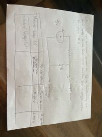
Please do the calculated voltage please. Please write all formulas and write clear

Transcribed Image Text:**Title: Understanding the Effect of Input Resistance in Circuit Design**
**Introduction:**
This educational guide explores the impact of input resistance on the measured and calculated voltage in a simple electrical circuit. We will examine how to set up the circuit using a DC power supply and interpret the data collected.
**Circuit Setup:**
1. **Power Source:** The circuit is powered by a 5V DC supply.
2. **Components:** The circuit includes a resistor connected in series with a voltmeter.
3. **Oscilloscope Connections:**
- Positive terminal connected through a resistor.
- Ground terminal connected to common ground.
**Procedure:**
- Connect the DC power supply set to 5V as shown in the diagram.
- Measure the voltage across the resistor using an oscilloscope.
**Data Collection:**
| Resistance (R) | Calculated Voltage (V) | Measured Voltage (V) |
|----------------|------------------------|----------------------|
| 72.355 k-ohms | 2.42 V | |
| 1 k-ohms | | 0.65 V |
| 10 k-ohms | | |
**Analysis:**
- The table above shows the calculated and measured voltages for different resistance values.
- Compare the measured voltages to the calculated ones to observe discrepancies and understand the influence of resistance on voltage reading accuracy.
**Conclusion:**
This experiment demonstrates the significance of considering input resistance in circuit design, especially when precise voltage measurements are required. Adjustments in resistance can lead to discernible differences in expected and actual voltages, highlighting the need for careful component selection and circuit configuration.
**Note:** Always double-check connections and component values during setup to ensure accurate results.
Expert Solution
This question has been solved!
Explore an expertly crafted, step-by-step solution for a thorough understanding of key concepts.
Step by stepSolved in 4 steps with 1 images

Knowledge Booster
Learn more about
Need a deep-dive on the concept behind this application? Look no further. Learn more about this topic, electrical-engineering and related others by exploring similar questions and additional content below.Similar questions
- Hello, can you help me convert to decimalarrow_forwardplease help with this three part question (parts a,b,c)arrow_forward8. We have two push buttons A and B. Design a 3-digit BCD counter that: - counts from 000 to 999 if no button is pressed - Resets the count to 555 if both push buttons A and B are pressed Resets the count to 222 if only push button A is pressed - Resets the count to 333 if only push button B is pressedarrow_forward
arrow_back_ios
arrow_forward_ios
Recommended textbooks for you
 Introductory Circuit Analysis (13th Edition)Electrical EngineeringISBN:9780133923605Author:Robert L. BoylestadPublisher:PEARSON
 Delmar's Standard Textbook Of ElectricityElectrical EngineeringISBN:9781337900348Author:Stephen L. HermanPublisher:Cengage Learning
 Programmable Logic ControllersElectrical EngineeringISBN:9780073373843Author:Frank D. PetruzellaPublisher:McGraw-Hill Education
 Fundamentals of Electric CircuitsElectrical EngineeringISBN:9780078028229Author:Charles K Alexander, Matthew SadikuPublisher:McGraw-Hill Education
 Electric Circuits. (11th Edition)Electrical EngineeringISBN:9780134746968Author:James W. Nilsson, Susan RiedelPublisher:PEARSON
 Engineering ElectromagneticsElectrical EngineeringISBN:9780078028151Author:Hayt, William H. (william Hart), Jr, BUCK, John A.Publisher:Mcgraw-hill Education,

Introductory Circuit Analysis (13th Edition)
Electrical Engineering
ISBN:9780133923605
Author:Robert L. Boylestad
Publisher:PEARSON

Delmar's Standard Textbook Of Electricity
Electrical Engineering
ISBN:9781337900348
Author:Stephen L. Herman
Publisher:Cengage Learning

Programmable Logic Controllers
Electrical Engineering
ISBN:9780073373843
Author:Frank D. Petruzella
Publisher:McGraw-Hill Education

Fundamentals of Electric Circuits
Electrical Engineering
ISBN:9780078028229
Author:Charles K Alexander, Matthew Sadiku
Publisher:McGraw-Hill Education

Electric Circuits. (11th Edition)
Electrical Engineering
ISBN:9780134746968
Author:James W. Nilsson, Susan Riedel
Publisher:PEARSON

Engineering Electromagnetics
Electrical Engineering
ISBN:9780078028151
Author:Hayt, William H. (william Hart), Jr, BUCK, John A.
Publisher:Mcgraw-hill Education,