Introductory Circuit Analysis (13th Edition)
13th Edition
ISBN: 9780133923605
Author: Robert L. Boylestad
Publisher: PEARSON
expand_more
expand_more
format_list_bulleted
Question
Please Help ASAP!!!!
Example 2.2 is also attached

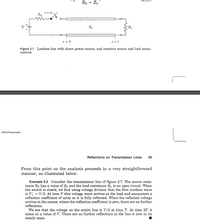
Transcribed Image Text:Rs + Zo
t = 0
Rs
Zo
R1
z = 0
Figure 2.7 Lossless line with direct power source, and resistive source and load termi-
nations.
MGH/Rosenstark
Reflections on Transmission Lines
29
From this point on the analysis proceeds in a very straightforward
manner, as illustrated below.
Example 2.2 Consider the transmission line of figure 2.7. The source resis-
tance Rs has a value of Zo and the load resistance RL is an open circuit. When
the switch is closed, we find using voltage division that the first incident wave
is V = V/2. At time T this voltage wave arrives at the load and encounters a
reflection coefficient of unity so it is fully reflected. When the reflected voltage
arrives at the source, where the reflection coefficient is zero, there are no further
reflections.
We see that the voltage on the entire line is V/2 at time T. At time 2T it
takes on a value of V. There are no further reflections so the line is now in its
steady state.

Transcribed Image Text:P2.5
Draw the voltage and current lattice-diagrams for example 2.2. From
l and z = l. Also draw
that, draw voltage and current waveforms at z =
voltage and current distributions for t = 3T/2.
Expert Solution
arrow_forward
Step 1
The answer to the above problem is provided in the following steps.
Step by stepSolved in 4 steps with 3 images

Knowledge Booster
Similar questions
- Compare microchip technologies for power management, such as voltage regulators and energy harvesting devices, and their relevance in energy-efficient IoT applications.arrow_forwardB//Define the following: 1- Unit load 2-Noise immunity 3-E2CMOSarrow_forwardPlease explain simply in detail, why Analog and Digital Electronics are important. Also please detail as many applications as possible and their relative usefullnesses.arrow_forward
Recommended textbooks for you
 Introductory Circuit Analysis (13th Edition)Electrical EngineeringISBN:9780133923605Author:Robert L. BoylestadPublisher:PEARSON
 Delmar's Standard Textbook Of ElectricityElectrical EngineeringISBN:9781337900348Author:Stephen L. HermanPublisher:Cengage Learning
 Programmable Logic ControllersElectrical EngineeringISBN:9780073373843Author:Frank D. PetruzellaPublisher:McGraw-Hill Education
 Fundamentals of Electric CircuitsElectrical EngineeringISBN:9780078028229Author:Charles K Alexander, Matthew SadikuPublisher:McGraw-Hill Education
 Electric Circuits. (11th Edition)Electrical EngineeringISBN:9780134746968Author:James W. Nilsson, Susan RiedelPublisher:PEARSON
 Engineering ElectromagneticsElectrical EngineeringISBN:9780078028151Author:Hayt, William H. (william Hart), Jr, BUCK, John A.Publisher:Mcgraw-hill Education,

Introductory Circuit Analysis (13th Edition)
Electrical Engineering
ISBN:9780133923605
Author:Robert L. Boylestad
Publisher:PEARSON

Delmar's Standard Textbook Of Electricity
Electrical Engineering
ISBN:9781337900348
Author:Stephen L. Herman
Publisher:Cengage Learning

Programmable Logic Controllers
Electrical Engineering
ISBN:9780073373843
Author:Frank D. Petruzella
Publisher:McGraw-Hill Education

Fundamentals of Electric Circuits
Electrical Engineering
ISBN:9780078028229
Author:Charles K Alexander, Matthew Sadiku
Publisher:McGraw-Hill Education

Electric Circuits. (11th Edition)
Electrical Engineering
ISBN:9780134746968
Author:James W. Nilsson, Susan Riedel
Publisher:PEARSON

Engineering Electromagnetics
Electrical Engineering
ISBN:9780078028151
Author:Hayt, William H. (william Hart), Jr, BUCK, John A.
Publisher:Mcgraw-hill Education,