Draw the block diagram of digital Multimeter and explain the measurement of D.C voltage


Draw the block diagram of digital Multimeter and explain the measurement of D.C voltage
Digital multi meter is a measuring device which is used to measure AC and DC voltages, AC and DC currents and resistance.
The figure below shows the block diagram of a digital multi meter
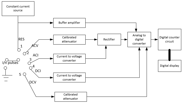
In the block diagram there are two input terminals, one of which is connected to the mode selector switch or rotatory switch, which decides the quantity to be measured, and the other terminal is connected to the common or negative. The rotatory switch has five positions where each position has separate functions which are marked in the block diagram. First position is designed for the resistance measurement. In the first position the input goes to the resistance measurement that is the unknown quantity here is the resistance. This unknown resistance should be a part of the potential divider circuit, so the constant current source in the block diagram provides the current to the resistance. Then we can find the value of R by applying ohms law. The buffer amplifier amplify the voltage which is developed across the unknown resistance. The buffer amplifier will amplify only the voltage that is developed across the unknown resistance. The unknown resistance can be measured from these current and voltage values.
The second position of the rotatory switch is for the measurement of AC voltage. Here the input signal is unknown AC voltage. Similarly there are positions for AC current, DC current, and DC voltage measurements.
After the measurement these measured analog signals will be converted into digital signals by an analog to digital converter. And will be displayed in a digital display unit.

Step by step
Solved in 3 steps with 1 images


