Related questions
Question
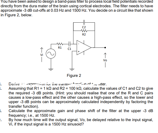

Transcribed Image Text:You have been asked to design a band-pass filter to process local field potentials recorded
directly from the dura mater of the brain using cortical electrodes. The filter needs to have
approximate -3 dB cut-offs at 0.03 Hz and 1500 Hz. You decide on a circuit like that shown
in Figure 2, below.
C2
R2
R1
C1
Vo
Figure 2
Derive = -xprersuLivi üre vansı-: *nati, in ot tu ilter.
i.
i.
Assuming that R1 = 1 kQ and R2 = 100 kQ, calculate the values of C1 and C2 to give
the required -3 dB points. (Hint: you should realise that one of the R and C pairs
causes a low-pass effect and the other causes a high-pass effect, so the lower and
upper -3 dB points can be approximately calculated independently by factoring the
transfer function).
i.
Calculate the approximate gain and phase shift of the filter at the upper -3 dB
frequency; i.e., at 1500 Hz.
By how much time will the output signal, Vo, be delayed relative to the input signal,
Vi, if the input signal is a 1500 Hz sinusoid?
Expert Solution
This question has been solved!
Explore an expertly crafted, step-by-step solution for a thorough understanding of key concepts.

Step by stepSolved in 4 steps with 8 images

Knowledge Booster

Similar questions
- give correct answerarrow_forwardPls help with the following, thank you Consider the circuit sketched in the figure (Figure 1). The source has a voltage amplitude of 240 V, R� = 140 Ω, and the reactance of the capacitor is 600 Ω. The voltage amplitude across the capacitor is 650 V. Part A. What is the current amplitude in the circuit? Express your answer in amperes. Part B. What is the impedance? Express your answer in ohms. Part C. What two values can the reactance of the inductor have? Express your answers in ohms separated by comma.arrow_forwardShow that perturbing an RLC circuit (like the one in the figure) in balance, evolves like a damped oscillator. a) What is the natural frequency of its oscillations? b) What is the characteristic damping time? c) Calculate the above values for a circuit with R = 2 Ω, C = 10^−3 F, L = 0.1 H.arrow_forward
- Please show the work, thank you.arrow_forwardThe current in the circuit shown in the figure below equals 64.0% of the peak current at t = 8.50 ms. What is the lowest source frequency that gives this current? Hz max sin 2ft R AV wwarrow_forwardThe figure below shows the current i and driving emf & for a series RLC circuit. "Ay Is the phase constant positive or negative? The phase constant is positive. The phase constant is negative.arrow_forward
arrow_back_ios
arrow_forward_ios