Elements Of Electromagnetics
7th Edition
ISBN: 9780190698614
Author: Sadiku, Matthew N. O.
Publisher: Oxford University Press
expand_more
expand_more
format_list_bulleted
Question
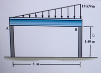
Diameter A da=140mm and diameter B db=140mm. What is the vertical displacement that occurs in the middle of the AB rigid beam?

Transcribed Image Text:18 kN/m
A
В
1.40 m
3 m-
Expert Solution
This question has been solved!
Explore an expertly crafted, step-by-step solution for a thorough understanding of key concepts.
Step by stepSolved in 4 steps with 2 images

Knowledge Booster
Learn more about
Need a deep-dive on the concept behind this application? Look no further. Learn more about this topic, mechanical-engineering and related others by exploring similar questions and additional content below.Similar questions
- Hi there sir/madam I need help on this question A beam with a solid homogeneous rectangular section is simply supported at A and B. A concentrated load F = 150 kilonewtons (kN) acts at point C where distance L1 (A to C) = 2.50 metres (m) and distance L2 (C to B) = 1.65 metres (m). The dimensions of the rectangular section of the beam are breadth, b = 35 mm and depth d = 125 mm. Calculate the maximum bending stress and give your answer in N/mm2 to two decimal placesarrow_forwardIf F1= 24kN F2=26kN F3=21.5kN Calculate the second area of moment of the beam using the dimensions in the attached imagearrow_forwardGiven the beam shown below, determine the shear force and bending moment at point C. Given the dimensions a = 2 m, b = 5.9 m and c = 2 m, and the load intensities e = 10 kN/m and f = 2 kN/m. e kN/m f kN/m am bm cm A B D Shear force (observe the up on the left, down on the right positive sign convention): SFc = Number Units (tolerance 0.2 kN) Bending moment (observe the sagging positive sign convention): BMc = Number Units (tolerance 1 kN*m)arrow_forward
- wo = 9 kN/m, L = 5.5 m, E = 220 GPa, and I = 100 x 10° mm4. A Part 1 Cut a cross-section through the beam at any point and draw a free body diagram to the right of your cut. Determine the internal bending moment M(x). The diagram shows M(x) in its positive direction. Your answer may be negative. Check your equation by solving for Mat x= 2.8 m. Wo M(x) L-x Answer: M(x = 2.8 m) = i kN-marrow_forwardA uniform beam is fixed at end x=0 and simply supported at x = L. Find the shape of the center line of the beam, given the weight per unit Length is w. a. b. C. e. O y(x) = d. y(x) = a y(x) = y(x) = y(x) = W 24 El -[x4 - 4Lx³ +6L²x²] =[x4-2Lx³ + L²x²] -[x4-2Lx³ + L³x] -[2x4-5Lx³+3L²x²] [2x4-3L³x³ +3L²x²] W 24 El W 24 El W 24 El - W 24 EIarrow_forwardI want the correct answers pleasearrow_forward
- Assume EI constant. For the beam below determine: A) The slope at point ? B) The displacement at the end point A Solve the problem using the 1) Conjugate-Beam Method and 2) Moment-Area Theorem. Please show all steps used as I am confused.arrow_forwardPlease only include the sketch mentioned in the question as I have already provided the calculation and answers to the question.arrow_forwardFor the eccentric loaded beam shown, determine the following:(a)Calculate the axial stress(b)Calculate the bending stress in the top and bottom layers of the beam(C)Determine the combined stress and sketch the combined stress profile in the beam sectionarrow_forward
- Can I get the correct answersarrow_forwardIf Mz = 200 kip-ft, find the magnitude of the bending stress at a point H. For the beam cross section, assume a = 7 in. b = 10 in. d = 26 in. r = 3.5 in. The centroid of the cross section is located 11.96 in. below the uppermost surface of the beam. The moment of inertia about the z axis is 12903 in.4.arrow_forwardA uniform beam is simply supported at both ends x = 0 and x = L. Find the shape of the center line of the beam, given the weight per unit Length is w. v(x) = [xª – 4 Lx3 + 6L?x²] 24 EI a. y(x) = [x4 – 2Lx3 + L?x²] 24 EI b. 2AEX1- 2Lx3 + L³x] 24 EI C. v(x) = v(x) = [2x4 -5 Lx3 + 3L?x²] 24 EI d. y(x) = [2x4 - 3L³x3 +3L²x²] е. 24 EIarrow_forward
arrow_back_ios
SEE MORE QUESTIONS
arrow_forward_ios
Recommended textbooks for you
 Elements Of ElectromagneticsMechanical EngineeringISBN:9780190698614Author:Sadiku, Matthew N. O.Publisher:Oxford University Press
 Mechanics of Materials (10th Edition)Mechanical EngineeringISBN:9780134319650Author:Russell C. HibbelerPublisher:PEARSON
 Thermodynamics: An Engineering ApproachMechanical EngineeringISBN:9781259822674Author:Yunus A. Cengel Dr., Michael A. BolesPublisher:McGraw-Hill Education
 Control Systems EngineeringMechanical EngineeringISBN:9781118170519Author:Norman S. NisePublisher:WILEY
 Mechanics of Materials (MindTap Course List)Mechanical EngineeringISBN:9781337093347Author:Barry J. Goodno, James M. GerePublisher:Cengage Learning
 Engineering Mechanics: StaticsMechanical EngineeringISBN:9781118807330Author:James L. Meriam, L. G. Kraige, J. N. BoltonPublisher:WILEY

Elements Of Electromagnetics
Mechanical Engineering
ISBN:9780190698614
Author:Sadiku, Matthew N. O.
Publisher:Oxford University Press

Mechanics of Materials (10th Edition)
Mechanical Engineering
ISBN:9780134319650
Author:Russell C. Hibbeler
Publisher:PEARSON

Thermodynamics: An Engineering Approach
Mechanical Engineering
ISBN:9781259822674
Author:Yunus A. Cengel Dr., Michael A. Boles
Publisher:McGraw-Hill Education

Control Systems Engineering
Mechanical Engineering
ISBN:9781118170519
Author:Norman S. Nise
Publisher:WILEY

Mechanics of Materials (MindTap Course List)
Mechanical Engineering
ISBN:9781337093347
Author:Barry J. Goodno, James M. Gere
Publisher:Cengage Learning

Engineering Mechanics: Statics
Mechanical Engineering
ISBN:9781118807330
Author:James L. Meriam, L. G. Kraige, J. N. Bolton
Publisher:WILEY