
Introductory Circuit Analysis (13th Edition)
13th Edition
ISBN: 9780133923605
Author: Robert L. Boylestad
Publisher: PEARSON
expand_more
expand_more
format_list_bulleted
Related questions
Question
i need the answer quickly
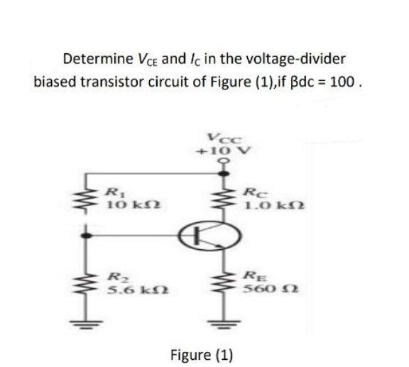

Transcribed Image Text:Determine VCE and Ic in the voltage-divider
biased transistor circuit of Figure (1),if Bdc = 100.
R₁
10 ΚΩ
R₂
5.6 ΚΩ
Vcc
+10 V
Figure (1)
Rc
1.0 ΚΩ
RE
560 Ω
Expert Solution
This question has been solved!
Explore an expertly crafted, step-by-step solution for a thorough understanding of key concepts.

Step by stepSolved in 4 steps with 2 images

Knowledge Booster


Learn more about
Need a deep-dive on the concept behind this application? Look no further. Learn more about this topic, electrical-engineering and related others by exploring similar questions and additional content below.Similar questions
- Base emitter and collector voltages please and thank you. Vcc= 12Varrow_forwardWhat is the Q-point for a biased transistor as in Figure F with Ig = 70μA, BDC 110, Vcc = 24V, and Rc = 3k2. 3kohm Rc= 01 Vout 2N2222A RB w IB = 70μΑ BDC= 110 VBB Figure F Vcc = 24Varrow_forwardThe data sheet of a JFET gives the following information: IDSS = 3 mA, VGS(off)= - 6 V, and gm(max)= 5000 . For VGS = - 4 V. find the drain current.arrow_forward
- 3. Design a four-resistor BJT bias circuit, similar to the one shown in Figure 2, such that V3 = 4 V and Ic = 1 mA. Assume VBE (on) = 0.7 V and B-150 for the transistor. 12V R1 R2 10k RC 5.6k Q2N2222 RE Figure 2 Note: Use PN2222A in Multisimarrow_forwardFor the circuit given in figure below draw the collector characteristic curves for IB = 50,150 and 250 micro amperes on the same grapharrow_forwardSolve the collector-emitter voltage (VCE) of Figure 612. vc 8V R1 3.3ka Beta = 110 VEE R2 -12V 3.9ka Figure 612 1.48V O -0.7V O - 0.86V O 0.7Varrow_forward
- Design a bias circuit for NPN silicon transistor having a nominal B-100 to be used in voltage divider circuit with Q-point of Ic 10 mA and VCE= 10 V. Use standard valued 5% resistors and draw a schematic %3D diagram of your designarrow_forwardAssume VRE 0.7 V and B-50 for the transistor in the circuit shown in the figure. For VCE = 2 V, the value of Rg is RB m B +12 V www Rc- 5 k C E VCEarrow_forwardProblem5: For the common base circurt shown in figure find I. and VCB. Assume transistor is Silicon (a-0.98) Ic Rp= 1.5 ko Rc= 1.2 kn VEE = 8 V. Vcc= 18 Varrow_forward
- 5. A JFET has a specified pinch-off voltage of 5 V. When VGs = 0, what is Vps at the point where the drain current becomes constant?arrow_forwardCollector characteristics for the Ge transistor If VEE =2 V, VCC =12V, and RC = 2k , size RE so that VCEQ = 6.4V. io mA ig-7 mA 6 mA 5 mA 4 mA Aic for hys Aig for he 3 mA Aic for hab Avea for h 2 mA I mA -10 -12 14 -16 -1- -20 "Carrow_forwardIf VCC = +18 V, voltage-divider resistor R1 is 4.7 kOhms, and R2 is 1500ohms, Solve for base bias voltage:4.35 V8.7 V2.9 V0.7 V Solve for VBE: 8.7 V0.3 V4.35 V0.7 Varrow_forward
arrow_back_ios
SEE MORE QUESTIONS
arrow_forward_ios
Recommended textbooks for you
- Introductory Circuit Analysis (13th Edition)Electrical EngineeringISBN:9780133923605Author:Robert L. BoylestadPublisher:PEARSON
 Delmar's Standard Textbook Of ElectricityElectrical EngineeringISBN:9781337900348Author:Stephen L. HermanPublisher:Cengage Learning
 Programmable Logic ControllersElectrical EngineeringISBN:9780073373843Author:Frank D. PetruzellaPublisher:McGraw-Hill Education
  Fundamentals of Electric CircuitsElectrical EngineeringISBN:9780078028229Author:Charles K Alexander, Matthew SadikuPublisher:McGraw-Hill Education
 Electric Circuits. (11th Edition)Electrical EngineeringISBN:9780134746968Author:James W. Nilsson, Susan RiedelPublisher:PEARSON
 Engineering ElectromagneticsElectrical EngineeringISBN:9780078028151Author:Hayt, William H. (william Hart), Jr, BUCK, John A.Publisher:Mcgraw-hill Education,
Introductory Circuit Analysis (13th Edition)
Electrical Engineering
ISBN:9780133923605
Author:Robert L. Boylestad
Publisher:PEARSON
Delmar's Standard Textbook Of Electricity
Electrical Engineering
ISBN:9781337900348
Author:Stephen L. Herman
Publisher:Cengage Learning
Programmable Logic Controllers
Electrical Engineering
ISBN:9780073373843
Author:Frank D. Petruzella
Publisher:McGraw-Hill Education
Fundamentals of Electric Circuits
Electrical Engineering
ISBN:9780078028229
Author:Charles K Alexander, Matthew Sadiku
Publisher:McGraw-Hill Education
Electric Circuits. (11th Edition)
Electrical Engineering
ISBN:9780134746968
Author:James W. Nilsson, Susan Riedel
Publisher:PEARSON
Engineering Electromagnetics
Electrical Engineering
ISBN:9780078028151
Author:Hayt, William H. (william Hart), Jr, BUCK, John A.
Publisher:Mcgraw-hill Education,