Introductory Circuit Analysis (13th Edition)
13th Edition
ISBN: 9780133923605
Author: Robert L. Boylestad
Publisher: PEARSON
expand_more
expand_more
format_list_bulleted
Question

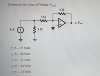
Transcribed Image Text:Determine the value of Voltage Vout
52
3 2
o Vout
6 A
3 2
O A. – 15 Volts
O B. – 20 Volts
O C.- 21 Volts
O D.- 24 Volts
O E.- 12 Volts
ww
Expert Solution
This question has been solved!
Explore an expertly crafted, step-by-step solution for a thorough understanding of key concepts.
This is a popular solution
Trending nowThis is a popular solution!
Step by stepSolved in 2 steps with 2 images

Knowledge Booster
Similar questions
- The power output of the half-wave rectifier is rated at 51.2 W with a load resistor of 20 ohms. The peak voltage at the output is: O A. 25 V O B. 203 V O C. None of the other choices are correct O D.51 V O E. 102.5 Varrow_forwardThe power output of the half-wave rectifier is rated at 25.6 W with a load resistor of 10 ohms. The average voltage at the output is: O A. 32 V O B. None of the other choices are correct O C. 8 V O D. 16 V O E. 64 Varrow_forwardQuestion (2) A controlled half-wave rectifier has a 240 V rms 60Hz ac source, The load a is R=30 Ohm resistor (a) Determine the delay angle such that the average load current is 2.5A (b) Determine the power absorbed by the load (c) Determine the power factor.arrow_forward
- 2. A bank of nickel-cadmium cells is used as the emergency lighting supply for a hospital. There are 100 cells connected in series and each has an A-hr rating of 120 A-hr. The bank has to be replaced, and the manufacturer is no longer supplying nickel-cadmium cells. It is decided to replace the cells with lead-acid cells. How many lead-acid cells will be required if each has an A-hr rating of 60 A-hr, and how should they be connected?arrow_forwardPlease help with the solution.arrow_forwardQuestion (2) A controlled half-wave rectifier has a 240 V rms 60Hz ac source, The load a is R=30 Ohm resistor (a) Determine the delay angle such that the average load current is 2.5A (b) Determine the power absorbed by the load (c) Determine the power factor.arrow_forward
- 2 Rectifier circuit determine the following show complete solutionarrow_forwardThe input to a full-wave rectifier is 10 V AC (RMS). The load resistor is 10 ohms and rectifier losses are 4W. The power efficiency of the rectifier is: O A. 58 % O B. None of the other choices are correct O C. 100 % O D. 80 % O E. 67 %arrow_forward
arrow_back_ios
arrow_forward_ios
Recommended textbooks for you
 Introductory Circuit Analysis (13th Edition)Electrical EngineeringISBN:9780133923605Author:Robert L. BoylestadPublisher:PEARSON
 Delmar's Standard Textbook Of ElectricityElectrical EngineeringISBN:9781337900348Author:Stephen L. HermanPublisher:Cengage Learning
 Programmable Logic ControllersElectrical EngineeringISBN:9780073373843Author:Frank D. PetruzellaPublisher:McGraw-Hill Education
 Fundamentals of Electric CircuitsElectrical EngineeringISBN:9780078028229Author:Charles K Alexander, Matthew SadikuPublisher:McGraw-Hill Education
 Electric Circuits. (11th Edition)Electrical EngineeringISBN:9780134746968Author:James W. Nilsson, Susan RiedelPublisher:PEARSON
 Engineering ElectromagneticsElectrical EngineeringISBN:9780078028151Author:Hayt, William H. (william Hart), Jr, BUCK, John A.Publisher:Mcgraw-hill Education,

Introductory Circuit Analysis (13th Edition)
Electrical Engineering
ISBN:9780133923605
Author:Robert L. Boylestad
Publisher:PEARSON

Delmar's Standard Textbook Of Electricity
Electrical Engineering
ISBN:9781337900348
Author:Stephen L. Herman
Publisher:Cengage Learning

Programmable Logic Controllers
Electrical Engineering
ISBN:9780073373843
Author:Frank D. Petruzella
Publisher:McGraw-Hill Education

Fundamentals of Electric Circuits
Electrical Engineering
ISBN:9780078028229
Author:Charles K Alexander, Matthew Sadiku
Publisher:McGraw-Hill Education

Electric Circuits. (11th Edition)
Electrical Engineering
ISBN:9780134746968
Author:James W. Nilsson, Susan Riedel
Publisher:PEARSON

Engineering Electromagnetics
Electrical Engineering
ISBN:9780078028151
Author:Hayt, William H. (william Hart), Jr, BUCK, John A.
Publisher:Mcgraw-hill Education,