Structural Analysis
6th Edition
ISBN: 9781337630931
Author: KASSIMALI, Aslam.
Publisher: Cengage,
expand_more
expand_more
format_list_bulleted
Question
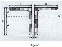
Determine the properties of the double
angle shown in the Figure 1 . The section is made
of 2 L 125 x 75 x 10 with long legs back-to-back
and spacing s = 5.60

Transcribed Image Text:B
y1
Figure 1
Expert Solution
This question has been solved!
Explore an expertly crafted, step-by-step solution for a thorough understanding of key concepts.
This is a popular solution
Trending nowThis is a popular solution!
Step by stepSolved in 3 steps with 3 images

Knowledge Booster
Learn more about
Need a deep-dive on the concept behind this application? Look no further. Learn more about this topic, civil-engineering and related others by exploring similar questions and additional content below.Similar questions
- A simple beam AB is loaded as shown in the figure. A В L L L 4 4 4 4 (a) Calculate the required section modulus S (in in.³) if oallow 18,000 psi, L = 15 ft, P = 3,250 lb, and q = 450 lb/ft. (At this point, disregard the weight of the beam.) 0.85286 X in. 3 Select a suitable I-beam (S shape) from this table, and recalculate S (in in.3), taking into account the weight of the beam. Select a new beam size if necessary. (Select the most economical beam size for your calculations.) 1.000 in. 3 What is the suitable beam size? O S6x 12.5 O S6x 17.2 O S 8× 23 O S 10 x 25.4 OS 8× 18.4 (b) What is the maximum load P that can be applied to your final beam selection in part (a)? (Enter the magnitude in Ib.) 3221 X Ibarrow_forwardThe simply supported wood beam is loaded as shown. Ewood=10 GPa What is the slope at A? What is the deflection at C?arrow_forwardThe force of an L-shaped round bar is shown in the figure below. Assuming that bending moment, torque and shear force effects need to be considered, try to calculate the vertical displacement of point C. E of the entire section is 200 GPa, G is 75 GPa, I, J The calculation with A assumes that the radius of the rod is 30 mm.arrow_forward
- I am studying for an exam and so I really need the step by step process guideline from the start to finish. For example: 1. Identify redundants 2. Solve for external/internal forces 3. etc.arrow_forwardDetermine:a) the horizontal displacement of joint A of the steel truss. b) Due to fabrication error, members AD and BE are 2cm too long. Determine the horizontal displacement of joint A under the same loading condition. Each member has a cross-sectional area of 400mm2 and E=200GPa.arrow_forwardThis "I-shaped" cross-section is often used for beams because the moment of inertia about the strong-axis is quite high, relative to the material used. Compute the moment of inertia about the strong-axis. Work smarter, not harder: you can either choose an additive method or a subtractive method. One is much faster than the other! Given: b=3"; c= 0.5"; e = 0.3"; f = 13.4" a C b 1$1 STRONG AXIS H + I 4 Ans: 283 inªarrow_forward
- 15. Refer to figure 6. Determine the elongation of the A-36 steel (E 200 GPa) member when it is subjected to an axial force P = 200 KN. The member is 10 mm thick and L = 0.5 m. a. 0.5004 mm b. 1.008 mm c. 1.889 mm d. 2.403 mm FIGURE 6 20 mm P 75 mmarrow_forwardA structural designer is experimenting with non-traditional cross-sections for beams. On the section shown, the triangular flanges have a width, b = 1.8 in. and height, h = 6 in. The top flange has a width, wf = 9.7 in. and a %3D %3D %3D thickness, t= 1.23 in. What is the second moment of area around the centroidal x axis, in in4? Wf barrow_forwardA beam cross section is shown. The dimensions are d = 7.6 in. and t = 0.40 in. The centroid of the cross section is located e = 3.782 in. above the bottom edge of the shape and f = 1.818 in. below the top edge. Calculate the moment of inertial for this cross section. Answer: N d y # in.4arrow_forward
- The last two digits of my redID is 89 for the problemarrow_forwardConsider the truss structure in the figure below. All diagonal members have axial stiffness EA, while the chord members have axial stiffness of 2EA. Using unit load method, find the vertical deflection at joint B. Feel free to use a spreadsheet to help with the tedious calculations, but please be sure the calculation steps are well set out.arrow_forwardHand written please .arrow_forward
arrow_back_ios
SEE MORE QUESTIONS
arrow_forward_ios
Recommended textbooks for you

 Structural Analysis (10th Edition)Civil EngineeringISBN:9780134610672Author:Russell C. HibbelerPublisher:PEARSON
 Principles of Foundation Engineering (MindTap Cou...Civil EngineeringISBN:9781337705028Author:Braja M. Das, Nagaratnam SivakuganPublisher:Cengage Learning
 Fundamentals of Structural AnalysisCivil EngineeringISBN:9780073398006Author:Kenneth M. Leet Emeritus, Chia-Ming Uang, Joel LanningPublisher:McGraw-Hill Education
 Traffic and Highway EngineeringCivil EngineeringISBN:9781305156241Author:Garber, Nicholas J.Publisher:Cengage Learning


Structural Analysis (10th Edition)
Civil Engineering
ISBN:9780134610672
Author:Russell C. Hibbeler
Publisher:PEARSON

Principles of Foundation Engineering (MindTap Cou...
Civil Engineering
ISBN:9781337705028
Author:Braja M. Das, Nagaratnam Sivakugan
Publisher:Cengage Learning

Fundamentals of Structural Analysis
Civil Engineering
ISBN:9780073398006
Author:Kenneth M. Leet Emeritus, Chia-Ming Uang, Joel Lanning
Publisher:McGraw-Hill Education


Traffic and Highway Engineering
Civil Engineering
ISBN:9781305156241
Author:Garber, Nicholas J.
Publisher:Cengage Learning