
Introductory Circuit Analysis (13th Edition)
13th Edition
ISBN: 9780133923605
Author: Robert L. Boylestad
Publisher: PEARSON
expand_more
expand_more
format_list_bulleted
Related questions
Question
Determine the output voltage waveform of the circuit.
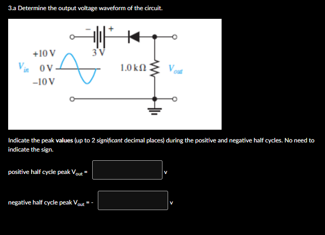

Transcribed Image Text:3.a Determine the output voltage waveform of the circuit.
+10 V
3'V
Vin ov
1.0 kΩ
Vout
-10 V
Indicate the peak values (up to 2 significant decimal places) during the positive and negative half cycles. No need to
indicate the sign.
positive half cycle peak Vout
negative half cycle peak Vout
Expert Solution
This question has been solved!
Explore an expertly crafted, step-by-step solution for a thorough understanding of key concepts.

This is a popular solution

Trending nowThis is a popular solution!

Step by stepSolved in 3 steps with 2 images

Knowledge Booster


Learn more about
Need a deep-dive on the concept behind this application? Look no further. Learn more about this topic, electrical-engineering and related others by exploring similar questions and additional content below.Similar questions
- Please answer the questions 1 c, and d with details on why it is true or false. Please make handwriting legible. Thank you.arrow_forwardDiscuss the significance of integrated circuits in the development of microchips, and provide examples of microchip applications.arrow_forwardDesign a circuit to measure AC power using pic microcontroller. 1. Write the circuit diagram. 2. List the required components. 3. Illustrate the required formulas for this operation. 4. Write the program for this application. 5. Display the measured reading on LCD.arrow_forward
- Helli. I only need the last part. Plotting power vs voltage if used as a solar cell and give the definition of fill factor. Tnxarrow_forwardOne component that does not need to be installed in the correct orientation is a: a. Resistorb. Diodec. Voltage regulatord.arrow_forwardCan someone please provide a step by step solution? Thank you! The full wave rectifier in the circuit below is to deliver 0.25A and 15V (peak) to a load. The ripple is to be no larger than 0.4 V peak-to-peak. The input signal is 120 V (rms) at 60 Hz. Assume V(lambda) = 0.7 V . Determine the required turns ratio, the filter capacitance, and the diode PIV rating.arrow_forward
- Draw the output waveform for the given circuit diagram with proper values and also mention the name of the circuit. The input waveform Vi is having a peak-to-peak value of 17 V and the bias voltage is 4 V. Assume diode to be silicon. Vo Maximum value of output waveform Minimum voltage of output waveformarrow_forwardb. Calculate the following about the circuit in the figure (If silicon diodes are employed in the rectification);i. the peak value of the output voltage considering the drop across each diode, Vpk.ii. the average voltage, Vdc. iii. The current through the load resistor, IL.iv. The current diode, Id.v. The frequency of the output signal, Fout.vi. Calculate the efficiency of the full wave rectifier expressed in percentage. vii. Sketch a graph of the input and output voltage against time.arrow_forward1. A six-pulse uncontrolled recti load. The inductance is very 1 (a) Determine average load o (b) Determine the maximum (c) Determine the maximum (d) Determine average loac (e) Carefully sketch the wav diode conduction pattern.arrow_forward
arrow_back_ios
arrow_forward_ios
Recommended textbooks for you
- Introductory Circuit Analysis (13th Edition)Electrical EngineeringISBN:9780133923605Author:Robert L. BoylestadPublisher:PEARSON
 Delmar's Standard Textbook Of ElectricityElectrical EngineeringISBN:9781337900348Author:Stephen L. HermanPublisher:Cengage Learning
 Programmable Logic ControllersElectrical EngineeringISBN:9780073373843Author:Frank D. PetruzellaPublisher:McGraw-Hill Education
  Fundamentals of Electric CircuitsElectrical EngineeringISBN:9780078028229Author:Charles K Alexander, Matthew SadikuPublisher:McGraw-Hill Education
 Electric Circuits. (11th Edition)Electrical EngineeringISBN:9780134746968Author:James W. Nilsson, Susan RiedelPublisher:PEARSON
 Engineering ElectromagneticsElectrical EngineeringISBN:9780078028151Author:Hayt, William H. (william Hart), Jr, BUCK, John A.Publisher:Mcgraw-hill Education,
Introductory Circuit Analysis (13th Edition)
Electrical Engineering
ISBN:9780133923605
Author:Robert L. Boylestad
Publisher:PEARSON
Delmar's Standard Textbook Of Electricity
Electrical Engineering
ISBN:9781337900348
Author:Stephen L. Herman
Publisher:Cengage Learning
Programmable Logic Controllers
Electrical Engineering
ISBN:9780073373843
Author:Frank D. Petruzella
Publisher:McGraw-Hill Education
Fundamentals of Electric Circuits
Electrical Engineering
ISBN:9780078028229
Author:Charles K Alexander, Matthew Sadiku
Publisher:McGraw-Hill Education
Electric Circuits. (11th Edition)
Electrical Engineering
ISBN:9780134746968
Author:James W. Nilsson, Susan Riedel
Publisher:PEARSON
Engineering Electromagnetics
Electrical Engineering
ISBN:9780078028151
Author:Hayt, William H. (william Hart), Jr, BUCK, John A.
Publisher:Mcgraw-hill Education,