
Structural Analysis
6th Edition
ISBN: 9781337630931
Author: KASSIMALI, Aslam.
Publisher: Cengage,
expand_more
expand_more
format_list_bulleted
Related questions
Concept explainers
Question
10.

Transcribed Image Text:**Title: Calculating the Moment of Inertia About the y-Axis**
**Objective:**
Understand how to determine the moment of inertia of a given area about the y-axis using the provided figures and options.
**Question:**
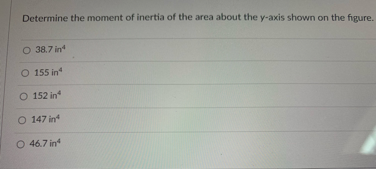
Determine the moment of inertia of the area about the y-axis shown on the figure.
**Options:**
- A) 38.7 in⁴
- B) 155 in⁴
- C) 152 in⁴
- D) 147 in⁴
- E) 46.7 in⁴
**Explanation:**
The moment of inertia is a measure of an object's resistance to rotation about an axis. It is integral in engineering and physics calculations regarding structural and material strength. The calculation often depends on the shape and distribution of the area with respect to the axis.
In this problem, you are required to select the correct moment of inertia of the given shape about the y-axis:
1. **Check the Units:**
- The moment of inertia values are given in in⁴, where "in" stands for inches, which is a typical unit used in the context of calculating moments of inertia for areas.
2. **Analyze the Area:**
- Although the specific figure is not shown here, typical shapes include rectangles, circles, I-beams, T-beams, among others. Each shape has its own formula for calculating the moment of inertia about an axis.
3. **Calculate Using the Appropriate Formula:**
- For common shapes, use standard formulas. Examples include:
- Rectangle: \( I_y = \frac{bh^3}{12} \)
- Circle: \( I_y = \frac{\pi r^4}{4} \)
- Complex shapes may require splitting into multiple simple shapes and applying the parallel axis theorem.
**Choosing the Correct Answer:**
- Compare the calculated moment of inertia with the provided options.
- Ensure the selected option matches your calculated value.
**Conclusion:**
Select the answer from the provided options that best matches the calculated moment of inertia for the shape about the y-axis, ensuring a precise application of relevant formulas and considering the configuration shown in the figure.
For further practice, try solving multiple problems with varying shapes and configurations to reinforce the concepts and formulas of calculating moments of inertia.

Transcribed Image Text:Welcome to our educational webpage! In this section, we discuss a fundamental mechanical engineering concept using a T-shaped diagram. Below is the detailed description and explanation of the diagram dimensions:
### Diagram Description (T-shaped Figure)
#### Vertical and Horizontal Axes
- **y-axis**: This axis runs vertically and intersects the horizontal x-axis at point A.
- **x-axis**: This axis runs horizontally and intersects the vertical y-axis at point A.
#### Key Points
- **Point A**: Intersection of the x and y axes at the bottom center of the vertical section.
- **Point B**: Located on the y-axis, 2 inches above Point A, at the intersection of the upper horizontal bar and the main vertical bar.
#### Dimensions
- **Horizontal Bar (Top of T)**
- Width (Span): 6 inches (3 inches on either side from Point B)
- Height: 2 inches
- **Vertical Bar (Stem of T)**
- Overall Height: 6 inches (4 inches from Point A to the bottom of the horizontal bar + 2 inches for the horizontal bar itself)
- Width: 2 inches aligned centrally with a 1-inch overlap on both sides at the bottom center.
#### Additional Measurements
- From the center of the vertical bar (Point A) at the bottom, there are two horizontal distances:
- **Left**: 2 inches from the center to the left edge.
- **Right**: 2 inches from the center to the right edge.
- The vertical bar extends 4 inches upwards from Point A to the start of the horizontal bar.
- On the bottom, there's an additional break in the horizontal width designated as 1 inch wide, which is balanced equally on both side edges.
This T-shaped figure is essential for engineering applications to understand material properties, structural balance, and stresses in a cross-section. Understanding these dimensions will aid in precise design and analysis tasks.
Expert Solution
This question has been solved!
Explore an expertly crafted, step-by-step solution for a thorough understanding of key concepts.

Step by stepSolved in 3 steps with 12 images

Knowledge Booster


Learn more about
Need a deep-dive on the concept behind this application? Look no further. Learn more about this topic, civil-engineering and related others by exploring similar questions and additional content below.Similar questions
- i need the answer quicklyarrow_forwardFind Ix for the shape below: 2.0 2.0 Ix: Componen Ai 1.0 |ΣΑΙ = Yave = [Aiyi/[Ai = dy = Yave - yi = |lx = Elxi + [A(dy2) = 3.0 8.0 yi Aiyi = Aiyi [lxi = Ixi dy ZA(dy)= Ai(dy)arrow_forwardFind the centroid of the shaded area shown. Units are in inches.arrow_forward
Recommended textbooks for you
 Structural Analysis (10th Edition)Civil EngineeringISBN:9780134610672Author:Russell C. HibbelerPublisher:PEARSON
 Principles of Foundation Engineering (MindTap Cou...Civil EngineeringISBN:9781337705028Author:Braja M. Das, Nagaratnam SivakuganPublisher:Cengage Learning
 Fundamentals of Structural AnalysisCivil EngineeringISBN:9780073398006Author:Kenneth M. Leet Emeritus, Chia-Ming Uang, Joel LanningPublisher:McGraw-Hill Education
 Traffic and Highway EngineeringCivil EngineeringISBN:9781305156241Author:Garber, Nicholas J.Publisher:Cengage Learning
Structural Analysis (10th Edition)
Civil Engineering
ISBN:9780134610672
Author:Russell C. Hibbeler
Publisher:PEARSON
Principles of Foundation Engineering (MindTap Cou...
Civil Engineering
ISBN:9781337705028
Author:Braja M. Das, Nagaratnam Sivakugan
Publisher:Cengage Learning
Fundamentals of Structural Analysis
Civil Engineering
ISBN:9780073398006
Author:Kenneth M. Leet Emeritus, Chia-Ming Uang, Joel Lanning
Publisher:McGraw-Hill Education
Traffic and Highway Engineering
Civil Engineering
ISBN:9781305156241
Author:Garber, Nicholas J.
Publisher:Cengage Learning