Introductory Circuit Analysis (13th Edition)
13th Edition
ISBN: 9780133923605
Author: Robert L. Boylestad
Publisher: PEARSON
expand_more
expand_more
format_list_bulleted
Concept explainers
Question
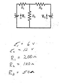
Determine the i1, i2 and i3.
Determine the power dissipated in each resistor.

Transcribed Image Text:Rg
E,
E= 6 v
12 v
Ri
= 200
Expert Solution
This question has been solved!
Explore an expertly crafted, step-by-step solution for a thorough understanding of key concepts.
Step by stepSolved in 3 steps with 3 images

Knowledge Booster
Learn more about
Need a deep-dive on the concept behind this application? Look no further. Learn more about this topic, electrical-engineering and related others by exploring similar questions and additional content below.Similar questions
- 1-18 What is the current of the circuit? A. Volts B. 5 Amps C. 5 Amps D. 2 Amps V1 -1 V A. W = V² x Q B. W = A² x Q C. W = A x V x Q D. W=Q/AX V R1 $0.50 Figure 1-7 Calculate the current in this circuit. 1-19 The watt (W) is the unit for electrical power, where P = I x V. Express the watt in terms of ohms (2), amperes (A), and/or volts (V): 1-20 Were your observations from the simulated circuit in the Simulate step consistent with your calculations from the Exercise step? If not, why do you think that is?arrow_forwardConsider the circuit given below. V₁ 192 552 992 www 3 V 60 752 If V₁ = 4 V, calculate the power dissipated by each resistor in the circuit. (Round the final answer to four decimal places.) The power dissipated by the 1-2 resistor is The power dissipated by the 6-2 resistor is The power dissipated by the 9-02 resistor is The power dissipated by the 7-22 resistor is The power dissipated by the 5-2 resistor is W. W. mW. W. W.arrow_forwardFor a basic electrical circuit what 3 components do you needarrow_forward
- Question #3 Imagine you have a Buzzer BZ1 with a resistance of 5600 and two lamps L1 and L2 with a resistance of 2002 each connected in series to a Battery of 6 Volt as shown in the diagram below 6V BZ1 - 560 Ohms. L1 20 Ohms L2-20 Ohms Calculate the power of the Buzzer BZ1, the Lamps L1 and L2 and the power of the Batteryarrow_forwardFor the circuit shown below, an ammeter connected across the output of the black box reads .04A while a voltmeter connected across the same two points reads 6V. Determine the equivalent Thevenin resistance and voltage as seen between those points.arrow_forward
arrow_back_ios
arrow_forward_ios
Recommended textbooks for you
 Introductory Circuit Analysis (13th Edition)Electrical EngineeringISBN:9780133923605Author:Robert L. BoylestadPublisher:PEARSON
 Delmar's Standard Textbook Of ElectricityElectrical EngineeringISBN:9781337900348Author:Stephen L. HermanPublisher:Cengage Learning
 Programmable Logic ControllersElectrical EngineeringISBN:9780073373843Author:Frank D. PetruzellaPublisher:McGraw-Hill Education
 Fundamentals of Electric CircuitsElectrical EngineeringISBN:9780078028229Author:Charles K Alexander, Matthew SadikuPublisher:McGraw-Hill Education
 Electric Circuits. (11th Edition)Electrical EngineeringISBN:9780134746968Author:James W. Nilsson, Susan RiedelPublisher:PEARSON
 Engineering ElectromagneticsElectrical EngineeringISBN:9780078028151Author:Hayt, William H. (william Hart), Jr, BUCK, John A.Publisher:Mcgraw-hill Education,

Introductory Circuit Analysis (13th Edition)
Electrical Engineering
ISBN:9780133923605
Author:Robert L. Boylestad
Publisher:PEARSON

Delmar's Standard Textbook Of Electricity
Electrical Engineering
ISBN:9781337900348
Author:Stephen L. Herman
Publisher:Cengage Learning

Programmable Logic Controllers
Electrical Engineering
ISBN:9780073373843
Author:Frank D. Petruzella
Publisher:McGraw-Hill Education

Fundamentals of Electric Circuits
Electrical Engineering
ISBN:9780078028229
Author:Charles K Alexander, Matthew Sadiku
Publisher:McGraw-Hill Education

Electric Circuits. (11th Edition)
Electrical Engineering
ISBN:9780134746968
Author:James W. Nilsson, Susan Riedel
Publisher:PEARSON

Engineering Electromagnetics
Electrical Engineering
ISBN:9780078028151
Author:Hayt, William H. (william Hart), Jr, BUCK, John A.
Publisher:Mcgraw-hill Education,