
Structural Analysis
6th Edition
ISBN: 9781337630931
Author: KASSIMALI, Aslam.
Publisher: Cengage,
expand_more
expand_more
format_list_bulleted
Related questions
Question
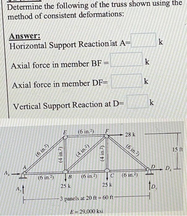

Transcribed Image Text:Determine the following of the truss shown using the
method of consistent deformations:
Answer:
Horizontal Support Reaction lat A=
k
Axial force in member BF =
Axial force in member DF=
Vertical Support Reaction at D=
E (6 in.2) F
A,
(6 in.²)
(6 in.²)
(4 in.²)
(4 in.²)
(4 in.²)
28 k
(6 in.²)
B
25 k
25 k
-3 panels at 20 ft = 60 ft-
E = 29,000 ksi
C (6 in.2)
(6 in.²)
k
k
k
15 ft
PDx.
tp.
Expert Solution
This question has been solved!
Explore an expertly crafted, step-by-step solution for a thorough understanding of key concepts.

This is a popular solution

Trending nowThis is a popular solution!

Step by stepSolved in 4 steps with 4 images

Knowledge Booster


Learn more about
Need a deep-dive on the concept behind this application? Look no further. Learn more about this topic, civil-engineering and related others by exploring similar questions and additional content below.Similar questions
- A thin polymer plate PQR is deformed so that corner Q is displaced downward by a distance L = 1.45 mm to new position Q' as shown. Determine the shear strain at Q' associated with the two edges (PQ and QR). 120 mm 480 mm. P R 240 mm -2692 μrad -3352 μrad O-4917 prad -3610 μrad O-2921 urad Q 'Q' Xarrow_forwardThe aluminum bar ACDB is rigidly connected to a steel tube in CD. The data is presented in the table. If the load P is equal to 125 kN, determine: The stress of aluminum in segment AC. Answ: 63.66 MPa The stress of aluminum in segment CD. Answ: 13.93 MPa The stress in steel in segment CD. Answ: 39.79 MPa The total deformation of the bar. Answ: 0.29273 mmarrow_forwardProblem 2 For the beam shown in the figure A) Draw the shear-force and bending-moment diagrams for the beam shown in the figure. B) For the composite section, aluminium [E = 70 GPa] bonded to a steel [E = 210 GPa], located at the maximum bending moment, determine: (1) the maximum bending stresses in the aluminium and steel bars. (2) the stress in the two materials at the joint where they are bonded together. K4N/M 2m B 10kN/mm 4m 2m D Steel Aluminum 42mm 20 mm 13 mmarrow_forward
- Part 2,3,4arrow_forwardPlease solve this question in hand wirting step by step.arrow_forwardA bronze pipe (1) is to be connected to an aluminum alloy pipe (2) at flange B. When put in place, however, a gap of A = 0.35 in. exists between the two pipes. Bronze pipe (1) has an elastic modulus of E1 = 16,000 ksi, a cross-sectional area of A1 = 2.66 in.?, and a length of L1 = 6.7 ft. Aluminum alloy pipe (2) has an elastic modulus of E2 = 10,000 ksi, a cross-sectional area of A2 = 1.37 in.2, and a length of L2 = 10.2 ft. If bolts are inserted in the flanges and tightened so that the gap at B is closed, determine: (a) the normal stresses produced in each of the members. (b) the final position of flange B with respect to support A. L2 В (1) Answer: (a) 01 = ksi 02 = ksi (b) ÕB/A = in.arrow_forward
- Problem 2 The rigid bar is plnned at A and held by two flexible bars at E and C. The load P Is applled at B. The two flexible bars FE and DC each have a diameter of 1 In. The flexible bars are elastic- perfectly plastic with a yleld stress equal to 20 ksl and a yleld strain of 0.001. Determine the following: The load R, at first yleld and the corresponding deflection at B, &, The ultimate load Pu and the corresponding deflection du The permanent deflection and residual stresses in each rod if the ultimate load is removed Construct P - A curve showing yield, ultimate and permanent deformation o (ksi) 1 ft E F 1 ft1 ft 20 B P e (in./in.) 0.001 1 ft D 2 ft 1 ft Aarrow_forwardA rod is composed of 3 segments shown in the figure and carries the axial loads, P1=120KN and P2=50KN. If the walls are rigid, determine the stress of bronze, aluminum, and steel in MPa.arrow_forward
arrow_back_ios
arrow_forward_ios
Recommended textbooks for you
 Structural Analysis (10th Edition)Civil EngineeringISBN:9780134610672Author:Russell C. HibbelerPublisher:PEARSON
 Principles of Foundation Engineering (MindTap Cou...Civil EngineeringISBN:9781337705028Author:Braja M. Das, Nagaratnam SivakuganPublisher:Cengage Learning
 Fundamentals of Structural AnalysisCivil EngineeringISBN:9780073398006Author:Kenneth M. Leet Emeritus, Chia-Ming Uang, Joel LanningPublisher:McGraw-Hill Education
 Traffic and Highway EngineeringCivil EngineeringISBN:9781305156241Author:Garber, Nicholas J.Publisher:Cengage Learning
Structural Analysis (10th Edition)
Civil Engineering
ISBN:9780134610672
Author:Russell C. Hibbeler
Publisher:PEARSON
Principles of Foundation Engineering (MindTap Cou...
Civil Engineering
ISBN:9781337705028
Author:Braja M. Das, Nagaratnam Sivakugan
Publisher:Cengage Learning
Fundamentals of Structural Analysis
Civil Engineering
ISBN:9780073398006
Author:Kenneth M. Leet Emeritus, Chia-Ming Uang, Joel Lanning
Publisher:McGraw-Hill Education
Traffic and Highway Engineering
Civil Engineering
ISBN:9781305156241
Author:Garber, Nicholas J.
Publisher:Cengage Learning