Structural Analysis
6th Edition
ISBN: 9781337630931
Author: KASSIMALI, Aslam.
Publisher: Cengage,
expand_more
expand_more
format_list_bulleted
Concept explainers
Question

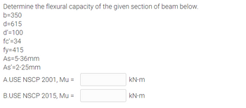
Transcribed Image Text:Determine the flexural capacity of the given section of beam below.
b=350
d=615
d'=100
fc'=34
fy=415
As-5-36mm
As'=2-25mm
A.USE NSCP 2001, Mu =
kN-m
B.USE NSCP 2015, Mu =
kN-m
Expert Solution
This question has been solved!
Explore an expertly crafted, step-by-step solution for a thorough understanding of key concepts.
Step by stepSolved in 3 steps with 3 images

Knowledge Booster
Learn more about
Need a deep-dive on the concept behind this application? Look no further. Learn more about this topic, civil-engineering and related others by exploring similar questions and additional content below.Similar questions
- Use A992 steel and select the lightest W shape. Use any design procedure.a. Use LRFD.b. Use ASD.arrow_forwardIn steel design use nscp 2015 i need a complete solutions ty..arrow_forwardGiven the truss shown, solve the following. Use A36 steel and assume there are two lines of three 19 mm bolts in each flange. Hole diameter is assumed to be three mm more than the bolt diameter. Neglect the weight of the section. a.What is the capacity of member CG? b. Design member CG using a W section. c. What is the tensile capacity of the section for CG based on gross area? The following W Section were considered for the design: W10x33 W14x38 W8x40 W16x36 W10x39 W8x13 189 KN 1.50 HL B 145 KN 1.50 E + 137 KN 121 KN -3.00 + 12.00 3.00 154 KN + W4x13 W6x9 W10x12 200 KN -1.50 1.50 1 030 T 1.20 +2.40 0.60 L i 0.30arrow_forward
arrow_back_ios
arrow_forward_ios
Recommended textbooks for you

 Structural Analysis (10th Edition)Civil EngineeringISBN:9780134610672Author:Russell C. HibbelerPublisher:PEARSON
 Principles of Foundation Engineering (MindTap Cou...Civil EngineeringISBN:9781337705028Author:Braja M. Das, Nagaratnam SivakuganPublisher:Cengage Learning
 Fundamentals of Structural AnalysisCivil EngineeringISBN:9780073398006Author:Kenneth M. Leet Emeritus, Chia-Ming Uang, Joel LanningPublisher:McGraw-Hill Education
 Traffic and Highway EngineeringCivil EngineeringISBN:9781305156241Author:Garber, Nicholas J.Publisher:Cengage Learning


Structural Analysis (10th Edition)
Civil Engineering
ISBN:9780134610672
Author:Russell C. Hibbeler
Publisher:PEARSON

Principles of Foundation Engineering (MindTap Cou...
Civil Engineering
ISBN:9781337705028
Author:Braja M. Das, Nagaratnam Sivakugan
Publisher:Cengage Learning

Fundamentals of Structural Analysis
Civil Engineering
ISBN:9780073398006
Author:Kenneth M. Leet Emeritus, Chia-Ming Uang, Joel Lanning
Publisher:McGraw-Hill Education


Traffic and Highway Engineering
Civil Engineering
ISBN:9781305156241
Author:Garber, Nicholas J.
Publisher:Cengage Learning