
Elements Of Electromagnetics
7th Edition
ISBN: 9780190698614
Author: Sadiku, Matthew N. O.
Publisher: Oxford University Press
expand_more
expand_more
format_list_bulleted
Question
Please solve the following by hand and without the use of AI. Use detailed mathematical formulas to solve the problem and do not use AI please. Thank You!
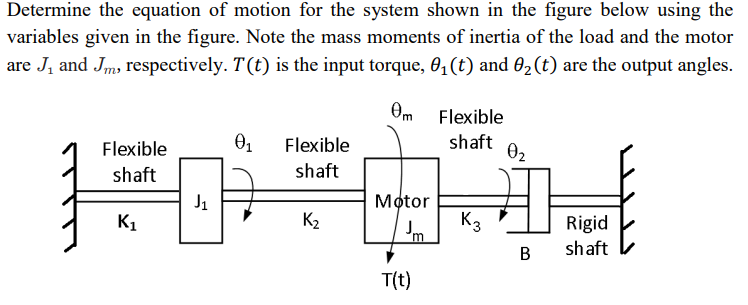

Transcribed Image Text:Determine the equation of motion for the system shown in the figure below using the
variables given in the figure. Note the mass moments of inertia of the load and the motor
are J₁ and Jm, respectively. T(t) is the input torque, 0₁ (t) and 02 (t) are the output angles.
Om Flexible
Flexible
shaft
01
Flexible
shaft
02
shaft
J1
Motor
K1
K₂
K3
Jm
Rigid
B
shaft
T(t)
Expert Solution
This question has been solved!
Explore an expertly crafted, step-by-step solution for a thorough understanding of key concepts.

Step by stepSolved in 2 steps with 2 images

Knowledge Booster

Similar questions
- Dear expert don't Use chat gptarrow_forward3- The single-degree-of-freedom "manipulator" shown below has total mass m = 1, with the center of mass at and has inertia tensor Rot ¹Pc: Ch= 100 020 002 'd From rest at t = 0, the joint angle 01 moves in accordance with the time function: 0₁ (t) = bt + ct² in radians. Give the angular acceleration of the link and the linear acceleration of the center of mass in terms of frame {1} as a function of t.arrow_forwardThe parameters in the system shown in Figure have the listed values m = 1.2 kg ID = 0.002 kg - m² r = 1 cm k = 3 × 10+ N/m Let x be the displacement of the mass center of the cart as the generalized coordinate. Derive the differential equation for the system using the equivalent systems method. Assume there is no friction between the cart and the surface. ID 2r marrow_forward
- 6. The electro-mechanical system shown below consists of an electric motor with input voltage V which drives inertia I in the mechanical system (see torque T). Find the governing differential equations of motion for this electro-mechanical system in terms of the input voltage to the motor and output displacement y. Electrical System puthiy C V V₁ R bac (0) T bac T Motor - Motor Input Voltage - Motor Back EMF = Kbac ( - Motor Angular Velocity - Motor Output Torque = K₂ i Kbacs K₁ - Motor Constants Mechanical System M T Frictionless Supportarrow_forwardPlease illustrate the graphs K = 2 N/m m = 1/2 kgarrow_forwardQ4-6 pleasearrow_forward
- Vibrations, show all steps and solutionsarrow_forwardFor the double slider mechanism shown in the following figure, the crank OA rotates at a uniform speed of 100 rad/s CW. we need to find the required torque for the crank, if two forces act at sliders B and C as shown in the figure. (P = 2KN, Q = 1KN). OA = 30 cm, AB = AC = 100 cm. mB = mC = 1 Kg. Neglect other links weights. The velocity of slip of slider B in m/s2 = Answer 1 Choose... The velocity of slip of slider C in m/s2 = Answer 2 Choose... The acceleration of slip of slider B in m/s2 = Answer 3 Choose... The acceleration of slip of slider C in m/s2 = Answer 4 Choose... The magnitude of required torque for the crank in N.m = Answer 5 Choose...arrow_forwardThe quarter-car model of a vehicle suspension and its free body diagram are shown in Figure 1. In this simplified model, the masses of the wheel, tire, and axle are neglected, and the mass m represents one-fourth of the vehicle mass. The spring constant k models the elasticity of both the tire and the suspension spring. The damping constant c models the shock absorber. The equilibrium position of m when y=0 is x=0. The road surface displacement y(t) can be derived from the road surface profile and the car’s speed. Draw free body diagram (FBD) and derive the equation of motion of m with y(t) as the input, and obtain the transfer function. If assume: m=300 kg k=20000, 40000, 60000 N/m c=1000, 3000, 5000 N.s/m Plot magnification ratio vs frequency ratio (r=0-4) diagrams for the parameters given above (you can draw the three curves in one diagram for three different k values and do the same for the three c values as well). Use the derived transfer function to model the system and plot…arrow_forward
- vibrations - solve and show solutionarrow_forwardMotor is driving a gear attached to the linkage in the mechanism as shown: Let r₁ r₂ = 10mm; c= 22mm; b= 100mm; a = 3mm; Determine the functions , of velocity of the slider with parameters (a,b,c) using the vector approach. (Hint: gears do not slip, link o-D is attached rigidly to the gear, pins at E and D allow free rotation) Schematic of kinematics: Velocity vector of point D: Velocity vector of point E: Equation of Velocity for the link E to F: b r₁ 12 Wmarrow_forwardThe mass m in the given figure is attached to a rigid rod with an inertia /about the pivot and negligible pivot friction. The input is the displacement z. When z= 0 = 0, the spring is at its free length. k ww L3 I a. Assuming that 0 is small, identify the equation of motion for e with z as the input. (Submit for Feedback using Connect) b. Use the Laplace transform method to determine the characteristic equation for this system. c. Solve this for the step response, 0(t), for the following system parameters and if the amplitude of the input step is z = 4 mm: System_Parameters = (k = = 100000.0 c = 1200.0 L = 0.03 L2= 0.04 L = 0.1 m= 2.0 I= 0.8 g=9.81 units : k - N; c~~ N.s. L1, L2, L2 ~ m; M ~ kg; 1 ~ kg · m²; g ~ ; m. m marrow_forward
arrow_back_ios
SEE MORE QUESTIONS
arrow_forward_ios
Recommended textbooks for you
- Elements Of ElectromagneticsMechanical EngineeringISBN:9780190698614Author:Sadiku, Matthew N. O.Publisher:Oxford University Press
 Mechanics of Materials (10th Edition)Mechanical EngineeringISBN:9780134319650Author:Russell C. HibbelerPublisher:PEARSON
 Thermodynamics: An Engineering ApproachMechanical EngineeringISBN:9781259822674Author:Yunus A. Cengel Dr., Michael A. BolesPublisher:McGraw-Hill Education
  Control Systems EngineeringMechanical EngineeringISBN:9781118170519Author:Norman S. NisePublisher:WILEY
 Mechanics of Materials (MindTap Course List)Mechanical EngineeringISBN:9781337093347Author:Barry J. Goodno, James M. GerePublisher:Cengage Learning
 Engineering Mechanics: StaticsMechanical EngineeringISBN:9781118807330Author:James L. Meriam, L. G. Kraige, J. N. BoltonPublisher:WILEY
Elements Of Electromagnetics
Mechanical Engineering
ISBN:9780190698614
Author:Sadiku, Matthew N. O.
Publisher:Oxford University Press
Mechanics of Materials (10th Edition)
Mechanical Engineering
ISBN:9780134319650
Author:Russell C. Hibbeler
Publisher:PEARSON
Thermodynamics: An Engineering Approach
Mechanical Engineering
ISBN:9781259822674
Author:Yunus A. Cengel Dr., Michael A. Boles
Publisher:McGraw-Hill Education
Control Systems Engineering
Mechanical Engineering
ISBN:9781118170519
Author:Norman S. Nise
Publisher:WILEY
Mechanics of Materials (MindTap Course List)
Mechanical Engineering
ISBN:9781337093347
Author:Barry J. Goodno, James M. Gere
Publisher:Cengage Learning
Engineering Mechanics: Statics
Mechanical Engineering
ISBN:9781118807330
Author:James L. Meriam, L. G. Kraige, J. N. Bolton
Publisher:WILEY