Introductory Circuit Analysis (13th Edition)
13th Edition
ISBN: 9780133923605
Author: Robert L. Boylestad
Publisher: PEARSON
expand_more
expand_more
format_list_bulleted
Concept explainers
Question

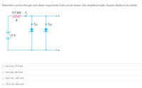
Transcribed Image Text:Determine current through each diode respectively in the circuit shown. Use simplified model. Assume diodes to be similar.
0.5 kN I1
R
Ipi
I2
15 V
O 14.3 mA, 17.4 mA
O 14.3 mA, 14.3 mA
O 18.9 mA, -18.9 mA
O -25.2 mA, 20.2 mA
Expert Solution
This question has been solved!
Explore an expertly crafted, step-by-step solution for a thorough understanding of key concepts.
Step by stepSolved in 2 steps with 1 images

Knowledge Booster
Learn more about
Need a deep-dive on the concept behind this application? Look no further. Learn more about this topic, electrical-engineering and related others by exploring similar questions and additional content below.Similar questions
- When a conventional Silicon diode is reversed-biased with a voltage high enough such that there is a very large current present, the voltage value this occurs at is referred to as the: a) Breakdown voltage b) Breakup voltage c) Hammer voltage d) Roller voltage O b O d O c a o o o oarrow_forwardFor the circuit shown below, sketch to scale the output V waveform and draw the transfer characteristic (V versus Vi), Assume the diodes are ideal.arrow_forwardSketch the output waveform and indicate the expected voltage levels for each of these diode circuits below. Use the diode models as indicated.arrow_forward
- For the circuit in the figure, let V input = 8V, Ri = 12ohms, RL = 10ohms, and VZ = 3.3V. Determine the voltages and currents of the resistors and the current of the zener diode.arrow_forwardA germanium diode has a current reaches 80% ofits saturation point at 115°C. Calculate the voltage and the ratio of the current for a forward bias of 0.8V to the current for the same magnitude in reverse bias when the temperature rises to 165°C.arrow_forwardWhat should be the value of Vi, if we have a Zener Diode with a breakdown voltage of 6.2 volts and a resistance of 1k ohms and a voltage reading ranging from 7.5 to 7.8 volts at 21ms on the simulation graph .arrow_forward
- 2. Design a clamper circuit to perform the function indicated. Vin th DESIGN Si diodes 10 V -10 V + Vin + Vout Vout 5.7 V -14.3 Varrow_forwardGiven the following circuit with VDD= 9.2 V, R=2.3 k2, then the current Iis: Use the CVD model for the diode, with VD = 0.65 V. I VDD a. 0.004000 A O b. 3.717391 A OC. 0 A d. 4.000000 A e. 0.003717 A R + VD -arrow_forwardWe know that the Si-diode will pass the current in a forward biased region. This behavior is useful for many applications. C)Plot the V-I Characteristic Curve of the diode.arrow_forward
- Consider diode circuit shown below with Vcc=5V and V₂ = 3V. U₁A HH +V₂ ū The peak inverse voltage on the diode is close to V₁ V. A Voarrow_forward4.) In which mode will a diode generally not conduct electricity? a. Bidirectional Biased b. None of these c. Forward Biased d. Reversed Biased 5.) Consider the following schematic symbol of a semiconductor device: Which side is the Cathode? (Picture inserted down below) a. Side A b. Both side A and B c. Side B d. Neither side A or B 8.) Integrated circuits can be broken down into three basic categories. Which category does an operational amplifier (or op-amp) fall into? a. Analog b. None of these c. A combination of analog and digital d. Digitalarrow_forwardB. For the circuit shown below, assume that the zener diode has Vz-3.3V and rz=092 when reverse biased, and has a 0.7V drop when forward biased. Fill the following table for values of Vo for different values of input voltage Vi. R1 Vi Vi -8V OV 8V 1k 5V N V2 R21k Vo Voarrow_forward
arrow_back_ios
SEE MORE QUESTIONS
arrow_forward_ios
Recommended textbooks for you
 Introductory Circuit Analysis (13th Edition)Electrical EngineeringISBN:9780133923605Author:Robert L. BoylestadPublisher:PEARSON
 Delmar's Standard Textbook Of ElectricityElectrical EngineeringISBN:9781337900348Author:Stephen L. HermanPublisher:Cengage Learning
 Programmable Logic ControllersElectrical EngineeringISBN:9780073373843Author:Frank D. PetruzellaPublisher:McGraw-Hill Education
 Fundamentals of Electric CircuitsElectrical EngineeringISBN:9780078028229Author:Charles K Alexander, Matthew SadikuPublisher:McGraw-Hill Education
 Electric Circuits. (11th Edition)Electrical EngineeringISBN:9780134746968Author:James W. Nilsson, Susan RiedelPublisher:PEARSON
 Engineering ElectromagneticsElectrical EngineeringISBN:9780078028151Author:Hayt, William H. (william Hart), Jr, BUCK, John A.Publisher:Mcgraw-hill Education,

Introductory Circuit Analysis (13th Edition)
Electrical Engineering
ISBN:9780133923605
Author:Robert L. Boylestad
Publisher:PEARSON

Delmar's Standard Textbook Of Electricity
Electrical Engineering
ISBN:9781337900348
Author:Stephen L. Herman
Publisher:Cengage Learning

Programmable Logic Controllers
Electrical Engineering
ISBN:9780073373843
Author:Frank D. Petruzella
Publisher:McGraw-Hill Education

Fundamentals of Electric Circuits
Electrical Engineering
ISBN:9780078028229
Author:Charles K Alexander, Matthew Sadiku
Publisher:McGraw-Hill Education

Electric Circuits. (11th Edition)
Electrical Engineering
ISBN:9780134746968
Author:James W. Nilsson, Susan Riedel
Publisher:PEARSON

Engineering Electromagnetics
Electrical Engineering
ISBN:9780078028151
Author:Hayt, William H. (william Hart), Jr, BUCK, John A.
Publisher:Mcgraw-hill Education,