
Elements Of Electromagnetics
7th Edition
ISBN: 9780190698614
Author: Sadiku, Matthew N. O.
Publisher: Oxford University Press
expand_more
expand_more
format_list_bulleted
Related questions
Concept explainers
Question
thumb_up100%
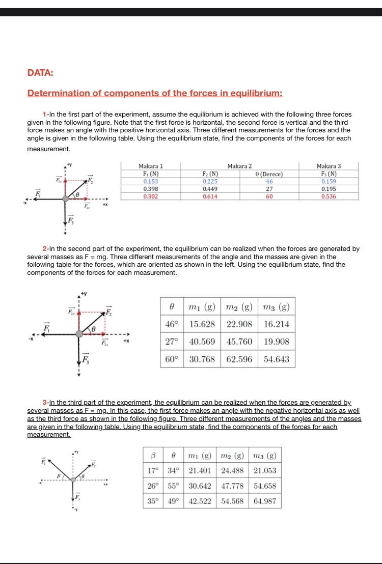

Transcribed Image Text:DATA:
Determination of components of the forces in equilibrium:
1-In the first part of the experiment, assume the equilibrium is achieved with the following three forces
given in the following figure. Note that the first force is horizontal, the second force is vertical and the third
force makes an angle with the positive horizontal axis. Three different measurements for the forces and the
angle is given in the following table. Using the equilibrium state, find the components of the forces for each
measurement.
F
F
F₂
Fay
F₂
Makara 1
F₁ (N)
0.153
0.398
0.302
F₂₁
F₂ (N)
0.225
0.449
0.614
Makara 2
2-In the second part of the experiment, the equilibrium can be realized when the forces are generated by
several masses as F = mg. Three different measurements of the angle and the masses are given in the
following table for the forces, which are oriented as shown in the left. Using the equilibrium state, find the
components of the forces for each measurement.
0 (Derece)
46
27
60
0
m₁ (g) m₂ (g)
m3 (g)
46°
15.628 22.908
16.214
27° 40.569 45.760 19.908
60° 30.768
62.596 54.643
Makara 3
F3 (N)
0.159
0.195
0.536
3m₁ (g) m2 (g) m3 (g)
17° 34° 21.401 24.488 21.053
26° 55° 30.642 47.778 54.658
35° 49° 42.522 54.568 64.987
3-In the third part of the experiment, the equilibrium can be realized when the forces are generated by.
several masses as F = mg. In this case, the first force makes an angle with the negative horizontal axis as well
as the third force as shown in the following figure. Three different measurements of the angles and the masses
are given in the following table. Using the equilibrium state, find the components of the forces for each
measurement.
*
Expert Solution
This question has been solved!
Explore an expertly crafted, step-by-step solution for a thorough understanding of key concepts.

This is a popular solution

Trending nowThis is a popular solution!

Step by stepSolved in 4 steps with 3 images

Knowledge Booster


Learn more about
Need a deep-dive on the concept behind this application? Look no further. Learn more about this topic, mechanical-engineering and related others by exploring similar questions and additional content below.Similar questions
- Determine the reaction forces at A and B. Follow sign convention.arrow_forwardTwo farmers are pushing on a gate with forces F_{A} and F_{B} applied at locations A and B respectively. The gate has a hinge at C and you may neglect the thickness of the gate. Assume that the gate is in static equilibrium. The force F_{A} is applied at an angle of alpha = 30 degrees and the force F_{B} is applied at an angle of beta = 35 degrees . The distance between B and the hinge at Cis D BC =2 m , and the distance between A and the hinge at C is D AC =3 m . Suppose that |F_{A}| = 400N Two farmers are pushing on a gate with forces F_{A} and F_{B} applied at locations A and B respectively. The gate has a hinge at C and you may neglect the thickness of the gate. Assume that the gate is in static equilibrium. The force F_{A} is applied at an angle of alpha = 30 degrees and the force F_{B} is applied at an angle of beta = 35 degrees . The distance between B and the hinge at Cis D BC =2 m , and the distance between A and the hinge at C is D AC =3 m . Suppose that |F_{A}| = 400N a)…arrow_forwardA force of Fi = (180 i -250j + 190k) lb is applied to the pipe assembly at point B. A force of F2 -250j + 250k) lb is applied to the pipe assembly at point D. The pipe assembly is supported by a fixed support at point A. (180 ? F1 В d3 C d1 d2 y F2 Values for the figure are given in the following table. Note the figure may not be to scale. Variable Value di 1 ft d2 2 ft dz 3.5 ft a. Determine the normal force at point C, Nc. Express as a Cartesian Vector. b. Determine the normal force at point C, Vc. Express as a Cartesian Vector. c. Determine the Torsional Moment at point C, Tc. Express as a Cartesian Vector. d. Determine the Bending Moment at point C, Bc. Express as a Cartesian Vector.arrow_forward
arrow_back_ios
arrow_forward_ios
Recommended textbooks for you
- Elements Of ElectromagneticsMechanical EngineeringISBN:9780190698614Author:Sadiku, Matthew N. O.Publisher:Oxford University Press
 Mechanics of Materials (10th Edition)Mechanical EngineeringISBN:9780134319650Author:Russell C. HibbelerPublisher:PEARSON
 Thermodynamics: An Engineering ApproachMechanical EngineeringISBN:9781259822674Author:Yunus A. Cengel Dr., Michael A. BolesPublisher:McGraw-Hill Education
  Control Systems EngineeringMechanical EngineeringISBN:9781118170519Author:Norman S. NisePublisher:WILEY
 Mechanics of Materials (MindTap Course List)Mechanical EngineeringISBN:9781337093347Author:Barry J. Goodno, James M. GerePublisher:Cengage Learning
 Engineering Mechanics: StaticsMechanical EngineeringISBN:9781118807330Author:James L. Meriam, L. G. Kraige, J. N. BoltonPublisher:WILEY
Elements Of Electromagnetics
Mechanical Engineering
ISBN:9780190698614
Author:Sadiku, Matthew N. O.
Publisher:Oxford University Press
Mechanics of Materials (10th Edition)
Mechanical Engineering
ISBN:9780134319650
Author:Russell C. Hibbeler
Publisher:PEARSON
Thermodynamics: An Engineering Approach
Mechanical Engineering
ISBN:9781259822674
Author:Yunus A. Cengel Dr., Michael A. Boles
Publisher:McGraw-Hill Education
Control Systems Engineering
Mechanical Engineering
ISBN:9781118170519
Author:Norman S. Nise
Publisher:WILEY
Mechanics of Materials (MindTap Course List)
Mechanical Engineering
ISBN:9781337093347
Author:Barry J. Goodno, James M. Gere
Publisher:Cengage Learning
Engineering Mechanics: Statics
Mechanical Engineering
ISBN:9781118807330
Author:James L. Meriam, L. G. Kraige, J. N. Bolton
Publisher:WILEY