Structural Analysis
6th Edition
ISBN: 9781337630931
Author: KASSIMALI, Aslam.
Publisher: Cengage,
expand_more
expand_more
format_list_bulleted
Concept explainers
Question
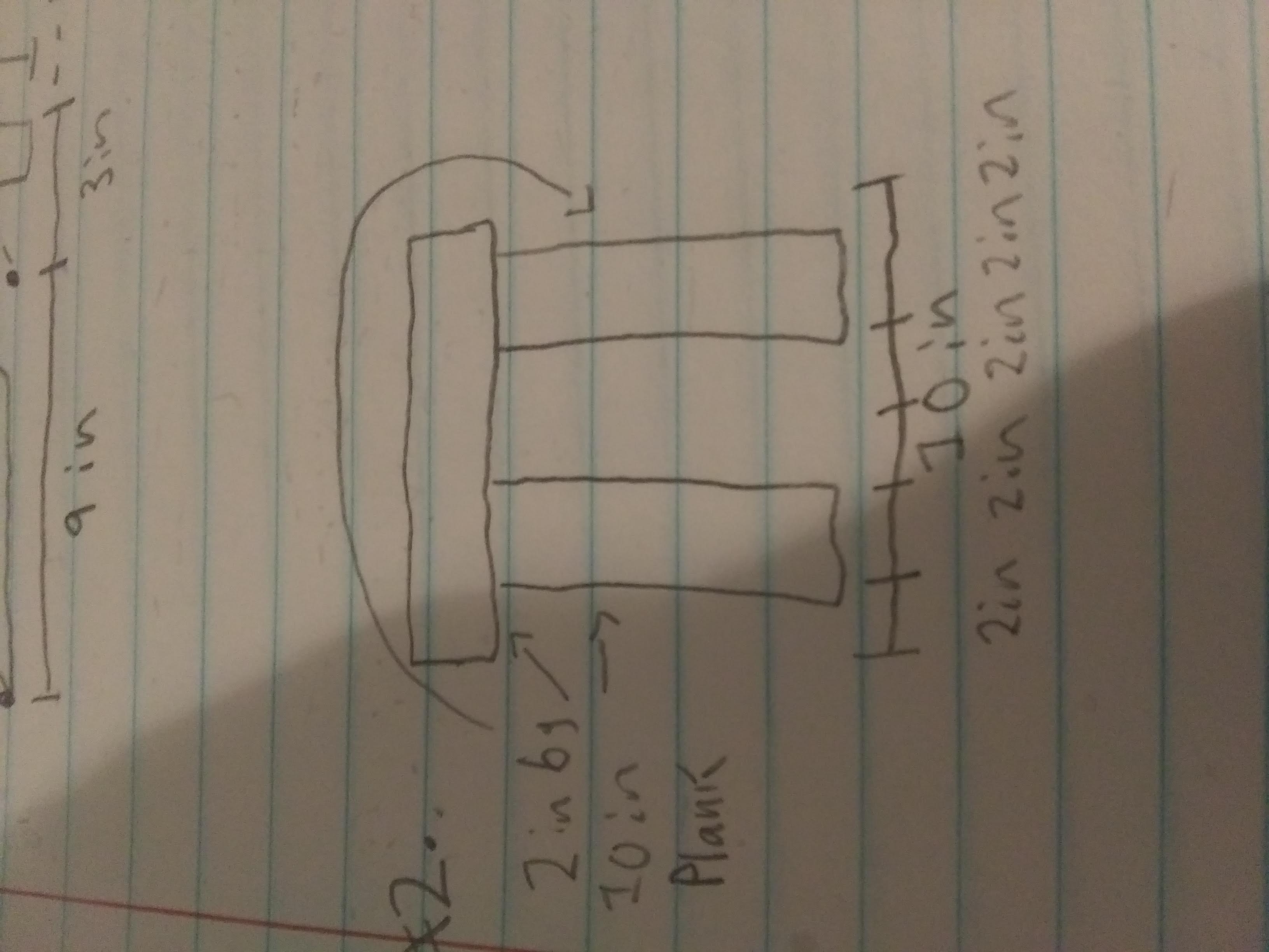
determin the moment of inertia of the figure shown with respect to the horizontal centroidal axis

Transcribed Image Text:Below is a transcription and description for an educational website.
---
### Diagram Explanation
This diagram appears to represent a simple structural plan for a small construction project involving a plank supported by two vertical beams. The following elements are included in the drawing:
**Top View Dimensions:**
- A plank measuring **9 inches** in length and **6 inches** in depth is shown.
- On the lower side of the diagram, there's an extension marked as **3 inches**.
**Side View Diagram and Dimensions:**
1. **Plank Dimensions:**
- The plank is marked as **2 inches by 6 inches** in size and labeled as "Plank".
- The total width of the entire top, including both vertical supports, is shown as **10 inches**.
2. **Vertical Supports:**
- Two vertical supports are depicted under the plank. These likely represent legs or beams.
3. **Base Dimensions:**
- The bottom section of the diagram indicates a total length of **10 inches**, composed of segments labeled as follows:
- **2 in, 2 in, 2 in, 2 in, 2 in**.
This structural plan likely serves as a basic guide for assembling a miniature model or a small-scale wooden project. Use these dimensions carefully when cutting and assembling materials to ensure stability and balance.
Expert Solution
This question has been solved!
Explore an expertly crafted, step-by-step solution for a thorough understanding of key concepts.
Step by stepSolved in 3 steps with 1 images

Knowledge Booster
Learn more about
Need a deep-dive on the concept behind this application? Look no further. Learn more about this topic, civil-engineering and related others by exploring similar questions and additional content below.Similar questions
Recommended textbooks for you

 Structural Analysis (10th Edition)Civil EngineeringISBN:9780134610672Author:Russell C. HibbelerPublisher:PEARSON
 Principles of Foundation Engineering (MindTap Cou...Civil EngineeringISBN:9781337705028Author:Braja M. Das, Nagaratnam SivakuganPublisher:Cengage Learning
 Fundamentals of Structural AnalysisCivil EngineeringISBN:9780073398006Author:Kenneth M. Leet Emeritus, Chia-Ming Uang, Joel LanningPublisher:McGraw-Hill Education
 Traffic and Highway EngineeringCivil EngineeringISBN:9781305156241Author:Garber, Nicholas J.Publisher:Cengage Learning


Structural Analysis (10th Edition)
Civil Engineering
ISBN:9780134610672
Author:Russell C. Hibbeler
Publisher:PEARSON

Principles of Foundation Engineering (MindTap Cou...
Civil Engineering
ISBN:9781337705028
Author:Braja M. Das, Nagaratnam Sivakugan
Publisher:Cengage Learning

Fundamentals of Structural Analysis
Civil Engineering
ISBN:9780073398006
Author:Kenneth M. Leet Emeritus, Chia-Ming Uang, Joel Lanning
Publisher:McGraw-Hill Education


Traffic and Highway Engineering
Civil Engineering
ISBN:9781305156241
Author:Garber, Nicholas J.
Publisher:Cengage Learning