Structural Analysis
6th Edition
ISBN: 9781337630931
Author: KASSIMALI, Aslam.
Publisher: Cengage,
expand_more
expand_more
format_list_bulleted
Concept explainers
Question

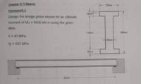
Transcribed Image Text:Chapter 3: T-Beams
Homework 1
700m
Design the bridge girder shown for an ultimate
moment of Mu = 5400 kN.m using the given
data.
110m
- 40 MPa
300mm
fy 520 MPa
150m
22.0m
Expert Solution
This question has been solved!
Explore an expertly crafted, step-by-step solution for a thorough understanding of key concepts.
Step by stepSolved in 3 steps

Knowledge Booster
Learn more about
Need a deep-dive on the concept behind this application? Look no further. Learn more about this topic, civil-engineering and related others by exploring similar questions and additional content below.Similar questions
- FOR THE TRUSS SHOW BELOW, SOLVE FOR THE STRESSES (ORANGE) IF ALL MEMBERS 750 mm^2.. 3m 2m 2m 2m C 3m E 200 KN 2m G F 100 kN H 4m Barrow_forwardi need solve in 20 min pleasearrow_forward! Required information NOTE: This is a multi-part question. Once an answer is submitted, you will be unable to return to this part. A frame and loading are shown. B P D of c 120 mm 120 mm 120 mm 90 mm ↓ Determine the force acting on member ABC at B. Take P = 440 N. (You must provide an answer before moving on to the next part.) The force acting on member ABC at Bis N.arrow_forward
- Determine the force in each member of the Pratt bridge truss shown in the figure, using the method of nodes. For each element, establish whether it is in tension or compression.arrow_forwardStatics Homework #7 Please label all answers Thank youarrow_forward*8-36 The frame supports a centrally applied distributed load of 1.8 kip/ft. Determine the state of stress at points A and B on member CD and indicate the results on a volume element located at each of these points. The pins at C and D are at the same location as the neutral axis for the cross section. 12 ft с A B 3 in. 3 in. 1 in. B 1.5 in. 6 in. E 16 ft- 1.8 kip/ft Darrow_forward
- Please show your complete solution. Thank you!arrow_forwardDetermine the reaction and member forces of the truss shown below using method of jointsarrow_forwardA Pratt roof truss is loaded as shown in the figure. Using the method of joints, determine the force in members CD, DE, and DF.arrow_forward
- Determine the maximum tensile or compressive stresses in the beam due to bending. The section has a base b= 140 mm and h= 240 mm PLACE THE ENTIRE PROCEDUREarrow_forwardThe steel is supported by the steel tie rod in AB beam B. Steel connection tension rod is placed 2 meters to the left of B and C sliding bracket is placed and P is loaded between AC It is. By ignoring the weights of beams and connecting rods, they can be determine the largest P load it can carry. The diameter of the BD rod is 16 mm. E = 200GPa I = 150x(10^6)mm^4arrow_forwardSolve the following problem and show your complete solutions. Explain your answer for better understanding.arrow_forward
arrow_back_ios
SEE MORE QUESTIONS
arrow_forward_ios
Recommended textbooks for you

 Structural Analysis (10th Edition)Civil EngineeringISBN:9780134610672Author:Russell C. HibbelerPublisher:PEARSON
 Principles of Foundation Engineering (MindTap Cou...Civil EngineeringISBN:9781337705028Author:Braja M. Das, Nagaratnam SivakuganPublisher:Cengage Learning
 Fundamentals of Structural AnalysisCivil EngineeringISBN:9780073398006Author:Kenneth M. Leet Emeritus, Chia-Ming Uang, Joel LanningPublisher:McGraw-Hill Education
 Traffic and Highway EngineeringCivil EngineeringISBN:9781305156241Author:Garber, Nicholas J.Publisher:Cengage Learning


Structural Analysis (10th Edition)
Civil Engineering
ISBN:9780134610672
Author:Russell C. Hibbeler
Publisher:PEARSON

Principles of Foundation Engineering (MindTap Cou...
Civil Engineering
ISBN:9781337705028
Author:Braja M. Das, Nagaratnam Sivakugan
Publisher:Cengage Learning

Fundamentals of Structural Analysis
Civil Engineering
ISBN:9780073398006
Author:Kenneth M. Leet Emeritus, Chia-Ming Uang, Joel Lanning
Publisher:McGraw-Hill Education


Traffic and Highway Engineering
Civil Engineering
ISBN:9781305156241
Author:Garber, Nicholas J.
Publisher:Cengage Learning