Introductory Circuit Analysis (13th Edition)
13th Edition
ISBN: 9780133923605
Author: Robert L. Boylestad
Publisher: PEARSON
expand_more
expand_more
format_list_bulleted
Question
thumb_up100%
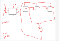
Design a 7 asynchronous countdown from 16 to 9. (Use JK or T type flip-flops
Below I have designed a 5 asynchronous countdown timer that counts from 7 to 2. It's in the photo (using JK or T type flip-flops)
I couldn't design the asynchronous back timer on top. Can you solve that question as in the photo below for me?

Expert Solution
This question has been solved!
Explore an expertly crafted, step-by-step solution for a thorough understanding of key concepts.
This is a popular solution
Trending nowThis is a popular solution!
Step by stepSolved in 2 steps with 2 images

Knowledge Booster
Learn more about
Need a deep-dive on the concept behind this application? Look no further. Learn more about this topic, electrical-engineering and related others by exploring similar questions and additional content below.Similar questions
- 2- Consider a state diagram shown below. Implement this state diagram using T (toggle) flip-flops and AND gates. What is the purpose of the circuit?arrow_forwardList out any one specific application for the four flip flops.arrow_forwardUsing 4 J-k flip flops explain how a counter can be built with the aid of a diagramarrow_forward
- asynchronous counters differs from a synchronous counter in * (a) the number of state in sequence (b) the method of clocking (c) the type of flip-flops used (d) the value of the modulusarrow_forwardAlert dont submit AI generated answer.arrow_forwardPLease Explain the design process of this thoroughlyarrow_forward
- 1. If a j-k flip flop has the j and k inputs connected to 5volts while being clocked it will: A. Toggle B. Enter the race condition C. Be set D. Be reset 2. What is the minimum number of J-K flip-flops needed to construct a divide by eight circuit? A.4 B.3 C.8 D.2arrow_forwardIn a J - K flip-flip we have J = Q and K = 1. Assuming the flip flop was initially cleared and then clocked for 6 puleses, the sequence at the Q output will be (a) 010000 (b) 011001 (c) 010010 (d) 010101arrow_forwardDraw a Moore-type state diagram and design a synchronous sequential circuit using D flip flops for a 1-input/1-output "sequence detector" for the sequence 11 (be sure to recognize overlapping sequences). Draw the final circuit. Draw a Moore-type state diagram and design a synchronous sequential circuit using D flip flops for a 1-input/1-output "sequence detector" for the sequence 100 (be sure to recognize overlapping sequences). Draw the final circuit. Draw a Moore-type state diagram and design a synchronous sequential circuit using D flip flops for a 1-input/1-output "sequence detector" for the sequence 110 (be sure to recognize overlapping sequences). Draw the final circuit. Draw a Moore-type state diagram and design a synchronous sequential circuit using D flip flops for a 1-input/1-output "sequence detector" for the sequence 000 (be sure to recognize overlapping sequences). Draw the final circuit. Draw a Moore-type state diagram and design a synchronous sequential circuit using D…arrow_forward
- Figure 2.1 shows the Asynchronous J-K flip flop and it truth table. Draw an output waveform, Q by drag and drop the correct waveform. Q is initially LOW. Clock Preset Clear Input J Input K Output J CLK K PRESET a Q CLEAR PRESET 1 0 CLEAR 1 1 0 0 Figure 2.1 FF response Clocked operation" Q1 (regardless of CLK) Q=0 (regardless of CLK) Not used 0 *Q will respond to J, K, and CLKarrow_forwardned the solve asap!arrow_forwardConsider the following circuit with 2 inputs (X and Y) and 2 J-K flip flops.· When X=0, the output (Q1Q0) preserves its value regardless of the value of Y.· When X=1 and Y=1, the output (Q1Q0) counts up by one (00-01-10-11-00 …).· When X=1 and Y=0, the output (Q1Q0) counts down by one (00-11-10-01-00 …). a) Derive the state transition, output table.b) Derive flip-flop excitations (logic expressions).c) Draw the circuit implementation using only 2-input NAND gates to drive the inputs J0and K0, and only multiplexers (MUX) to drive the inputs J1 and K1.arrow_forward
arrow_back_ios
SEE MORE QUESTIONS
arrow_forward_ios
Recommended textbooks for you
 Introductory Circuit Analysis (13th Edition)Electrical EngineeringISBN:9780133923605Author:Robert L. BoylestadPublisher:PEARSON
 Delmar's Standard Textbook Of ElectricityElectrical EngineeringISBN:9781337900348Author:Stephen L. HermanPublisher:Cengage Learning
 Programmable Logic ControllersElectrical EngineeringISBN:9780073373843Author:Frank D. PetruzellaPublisher:McGraw-Hill Education
 Fundamentals of Electric CircuitsElectrical EngineeringISBN:9780078028229Author:Charles K Alexander, Matthew SadikuPublisher:McGraw-Hill Education
 Electric Circuits. (11th Edition)Electrical EngineeringISBN:9780134746968Author:James W. Nilsson, Susan RiedelPublisher:PEARSON
 Engineering ElectromagneticsElectrical EngineeringISBN:9780078028151Author:Hayt, William H. (william Hart), Jr, BUCK, John A.Publisher:Mcgraw-hill Education,

Introductory Circuit Analysis (13th Edition)
Electrical Engineering
ISBN:9780133923605
Author:Robert L. Boylestad
Publisher:PEARSON

Delmar's Standard Textbook Of Electricity
Electrical Engineering
ISBN:9781337900348
Author:Stephen L. Herman
Publisher:Cengage Learning

Programmable Logic Controllers
Electrical Engineering
ISBN:9780073373843
Author:Frank D. Petruzella
Publisher:McGraw-Hill Education

Fundamentals of Electric Circuits
Electrical Engineering
ISBN:9780078028229
Author:Charles K Alexander, Matthew Sadiku
Publisher:McGraw-Hill Education

Electric Circuits. (11th Edition)
Electrical Engineering
ISBN:9780134746968
Author:James W. Nilsson, Susan Riedel
Publisher:PEARSON

Engineering Electromagnetics
Electrical Engineering
ISBN:9780078028151
Author:Hayt, William H. (william Hart), Jr, BUCK, John A.
Publisher:Mcgraw-hill Education,