Introductory Circuit Analysis (13th Edition)
13th Edition
ISBN: 9780133923605
Author: Robert L. Boylestad
Publisher: PEARSON
expand_more
expand_more
format_list_bulleted
Concept explainers
Question

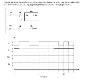
Transcribed Image Text:Describe the timing diagram for output Q1 based on the following PLC ladder logic diagram where T001
is an ON Delay Timer given the input signals 11 and 12 as shown in the timing diagram below.
TO01
11
12
TO01
10
11
12
TO01
Q1
1
0
1
0
1
0
1
0
0
V
1s
11
Trg
T
Q1
ΤΟΝ
5
Time (sec)
Expert Solution
This question has been solved!
Explore an expertly crafted, step-by-step solution for a thorough understanding of key concepts.
Step by stepSolved in 2 steps with 1 images

Knowledge Booster
Learn more about
Need a deep-dive on the concept behind this application? Look no further. Learn more about this topic, electrical-engineering and related others by exploring similar questions and additional content below.Similar questions
- Assume a single cycle architecture were the maximum delay of in its instruction set is 10 ns and minimum delay is 2 ns, then the operational frequency is: a. 1GHz b. 500MHz c.100Mhz d. 50MHz e. 10MHz d. 5MHz f. 1MHzarrow_forwardY=f(A,B,C)=(0,4,5)+don't care(2)arrow_forward30) Coils labeled ( S ) and ( R )A) must appear in that order (S before R) in a ladder logic programB) may be used only in subroutines in programs for Siemens PLCsC) are Short and Repeated coils, used in timing programsD) may be used instead of a seal-in arrangement to provide latchingarrow_forward
- a) An 8-bit shift register holds the data word 00111100. What will the register contents be after three right shifts? (Assume that serial input=D0) b) Draw the above shift register circuit using negative edge triggered D FFsarrow_forwardThe practical inverters output voltage normally is OSinusoidal waveform ONon-Sinusoidal waveform OQuasi-square waveformarrow_forwardConstruct a timing diagram with all the possible inputs and output for the logiccircuit shown in Figure Q2(d).arrow_forward
- Q1: Design and Draw the timing Diagram of 3-bit Asynchronous down counter if you know that the clock type is given in the figure below?arrow_forwardNeed complete correct and urgent answer.arrow_forwardWhat is setup time and hold time for a sequential circuit. Draw schematically a timing diagram showing the setup time and hold time for an input data signal, and draw the corresponding output data signal along with a clock signalarrow_forward
arrow_back_ios
arrow_forward_ios
Recommended textbooks for you
 Introductory Circuit Analysis (13th Edition)Electrical EngineeringISBN:9780133923605Author:Robert L. BoylestadPublisher:PEARSON
 Delmar's Standard Textbook Of ElectricityElectrical EngineeringISBN:9781337900348Author:Stephen L. HermanPublisher:Cengage Learning
 Programmable Logic ControllersElectrical EngineeringISBN:9780073373843Author:Frank D. PetruzellaPublisher:McGraw-Hill Education
 Fundamentals of Electric CircuitsElectrical EngineeringISBN:9780078028229Author:Charles K Alexander, Matthew SadikuPublisher:McGraw-Hill Education
 Electric Circuits. (11th Edition)Electrical EngineeringISBN:9780134746968Author:James W. Nilsson, Susan RiedelPublisher:PEARSON
 Engineering ElectromagneticsElectrical EngineeringISBN:9780078028151Author:Hayt, William H. (william Hart), Jr, BUCK, John A.Publisher:Mcgraw-hill Education,

Introductory Circuit Analysis (13th Edition)
Electrical Engineering
ISBN:9780133923605
Author:Robert L. Boylestad
Publisher:PEARSON

Delmar's Standard Textbook Of Electricity
Electrical Engineering
ISBN:9781337900348
Author:Stephen L. Herman
Publisher:Cengage Learning

Programmable Logic Controllers
Electrical Engineering
ISBN:9780073373843
Author:Frank D. Petruzella
Publisher:McGraw-Hill Education

Fundamentals of Electric Circuits
Electrical Engineering
ISBN:9780078028229
Author:Charles K Alexander, Matthew Sadiku
Publisher:McGraw-Hill Education

Electric Circuits. (11th Edition)
Electrical Engineering
ISBN:9780134746968
Author:James W. Nilsson, Susan Riedel
Publisher:PEARSON

Engineering Electromagnetics
Electrical Engineering
ISBN:9780078028151
Author:Hayt, William H. (william Hart), Jr, BUCK, John A.
Publisher:Mcgraw-hill Education,