Concept explainers
Derive the mutual-inductance of 2-winding IT in terms of the physical parameters of the transformer.

To derive the mutual-inductance of 2 winding inductive turn in terms of the physical parameter of the transformer. Let L1 and L2 is the self-inductance of the primary and secondary winding.
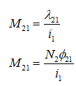
Mutual inductance is defines the flux of the coil 2 linking with coil 1, λ12. To the current flowing in coil 2.

Flux linkage of the coil from the 2 to the coil 1. Hence,

Similarly, mutual inductance of coil 1 to the coil 2,

Now assume that all flux produced by each coil links with the other coil. The implication of this is that there is no leakage flux.
The flux from coil 2 linking with coil 1 is equal to the flux from coil 2 linking with coil 2.

Step by stepSolved in 3 steps with 7 images

- (a) An ideal single-phase two-winding transformer with turns ratio at = N1/N2 is connected with a series impedance Z2 across winding 2. If one wants to replace 22, with a series impedance Z1 across winding 1 and keep the terminal behavior of the two circuits to be identical, find Z1 in terms of Z2.arrow_forwardA transformer having a nominal voltage = 399V and a no load voltage = 420V at its secondary, the short circuit current at the secondary of this transformer in function of its nominal current will be: Select one: Isc=10*In None of these Isc=30*In Isc=20*In Isc=40*Inarrow_forward4. What are the advantages of Delta connection in high power transformer?arrow_forward
- What conclusions we come up with after doing open circuit test on single phase transformer.arrow_forwardQ1) A 20KVA , 2000/200 V single phase ,50 Hz transformer has a primary resistance of 2.5 0 and reactance of 4.8 Q .the secondary resistance and reactance are 0.01 Q and 0.018 0 respectively .find a- equivalent resistance ,reactance and impedance referred to primary. b- equivalent resistance ,reactance and impedance referred to secondary.arrow_forwardfigure the S-parameters for an ideal transformer with turn ratio N = N1:N2 where N1 is the no.of turns of the primary winding and N2 is the no. of turns of the secondary winding.arrow_forward
 Introductory Circuit Analysis (13th Edition)Electrical EngineeringISBN:9780133923605Author:Robert L. BoylestadPublisher:PEARSON
 Delmar's Standard Textbook Of ElectricityElectrical EngineeringISBN:9781337900348Author:Stephen L. HermanPublisher:Cengage Learning
 Programmable Logic ControllersElectrical EngineeringISBN:9780073373843Author:Frank D. PetruzellaPublisher:McGraw-Hill Education
 Fundamentals of Electric CircuitsElectrical EngineeringISBN:9780078028229Author:Charles K Alexander, Matthew SadikuPublisher:McGraw-Hill Education
 Electric Circuits. (11th Edition)Electrical EngineeringISBN:9780134746968Author:James W. Nilsson, Susan RiedelPublisher:PEARSON
 Engineering ElectromagneticsElectrical EngineeringISBN:9780078028151Author:Hayt, William H. (william Hart), Jr, BUCK, John A.Publisher:Mcgraw-hill Education,


