
Introductory Circuit Analysis (13th Edition)
13th Edition
ISBN: 9780133923605
Author: Robert L. Boylestad
Publisher: PEARSON
expand_more
expand_more
format_list_bulleted
Related questions
Question
derive the mathematical model and find the transfer function please
Please answer in typing format please
I will like it please ASAP
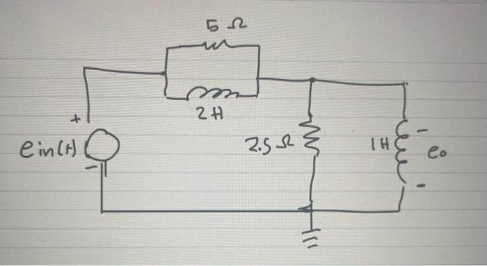

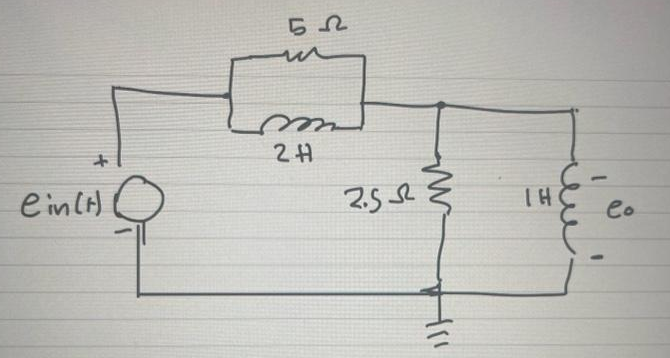
Transcribed Image Text:This diagram represents an electrical circuit with the following components:
1. **Voltage Source**: Represented by \( e_{in}(t) \), which is the input voltage source on the left side of the circuit.
2. **Resistor**: Located at the top of the circuit with a resistance of 5 ohms (5 Ω).
3. **Inductor**: Next to the 5 Ω resistor in series, with an inductance of 2 henries (2 H).
4. **Second Resistor**: Connected in series after the 2 H inductor, with a resistance of 2.5 ohms (2.5 Ω).
5. **Ground**: Connected by a line from the junction between the 2.5 Ω resistor and the 1 H inductor, showing common ground connection for the circuit.
6. **Inductor**: To the right, a second inductor with an inductance of 1 henry (1 H) is drawn in parallel with the output terminal.
7. **Output Voltage**: Labeled as \( e_o \), located parallel to the 1 H inductor on the right side of the circuit.
This series-parallel configuration is typical in analyzing circuits with complex impedance, focusing on the relationships and effects of different electrical components on circuit behavior.
Expert Solution
arrow_forward
Step 1: what is given and what to do:
Given:
a circuit,
we need to derive the transfer function of the system.

Trending nowThis is a popular solution!

Step by stepSolved in 3 steps with 7 images

Knowledge Booster


Learn more about
Need a deep-dive on the concept behind this application? Look no further. Learn more about this topic, electrical-engineering and related others by exploring similar questions and additional content below.Similar questions
- How many states required to design an FSM machine to process the following sequence, 000111000 6 9. 2.arrow_forwardShow a step by step solution.arrow_forwardDraw a circuit block of a 4-1, 8-1, and 16-1 MUX. For each MUX, identify and label the data selector, data inputs, and output. Also explain the number of input and selector data of each MUX.arrow_forward
arrow_back_ios
arrow_forward_ios
Recommended textbooks for you
- Introductory Circuit Analysis (13th Edition)Electrical EngineeringISBN:9780133923605Author:Robert L. BoylestadPublisher:PEARSON
 Delmar's Standard Textbook Of ElectricityElectrical EngineeringISBN:9781337900348Author:Stephen L. HermanPublisher:Cengage Learning
 Programmable Logic ControllersElectrical EngineeringISBN:9780073373843Author:Frank D. PetruzellaPublisher:McGraw-Hill Education
  Fundamentals of Electric CircuitsElectrical EngineeringISBN:9780078028229Author:Charles K Alexander, Matthew SadikuPublisher:McGraw-Hill Education
 Electric Circuits. (11th Edition)Electrical EngineeringISBN:9780134746968Author:James W. Nilsson, Susan RiedelPublisher:PEARSON
 Engineering ElectromagneticsElectrical EngineeringISBN:9780078028151Author:Hayt, William H. (william Hart), Jr, BUCK, John A.Publisher:Mcgraw-hill Education,
Introductory Circuit Analysis (13th Edition)
Electrical Engineering
ISBN:9780133923605
Author:Robert L. Boylestad
Publisher:PEARSON
Delmar's Standard Textbook Of Electricity
Electrical Engineering
ISBN:9781337900348
Author:Stephen L. Herman
Publisher:Cengage Learning
Programmable Logic Controllers
Electrical Engineering
ISBN:9780073373843
Author:Frank D. Petruzella
Publisher:McGraw-Hill Education
Fundamentals of Electric Circuits
Electrical Engineering
ISBN:9780078028229
Author:Charles K Alexander, Matthew Sadiku
Publisher:McGraw-Hill Education
Electric Circuits. (11th Edition)
Electrical Engineering
ISBN:9780134746968
Author:James W. Nilsson, Susan Riedel
Publisher:PEARSON
Engineering Electromagnetics
Electrical Engineering
ISBN:9780078028151
Author:Hayt, William H. (william Hart), Jr, BUCK, John A.
Publisher:Mcgraw-hill Education,