
Introductory Circuit Analysis (13th Edition)
13th Edition
ISBN: 9780133923605
Author: Robert L. Boylestad
Publisher: PEARSON
expand_more
expand_more
format_list_bulleted
Related questions
Question
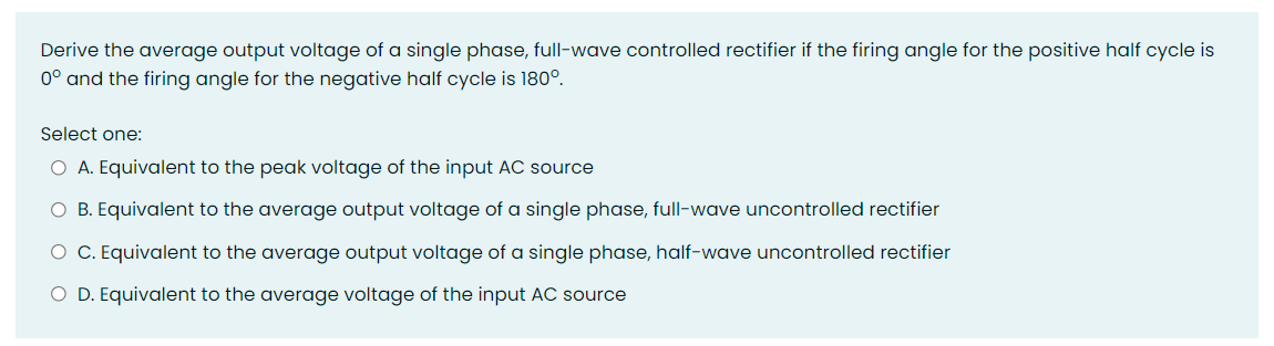

Transcribed Image Text:Derive the average output voltage of a single phase, full-wave controlled rectifier if the firing angle for the positive half cycle is
0° and the firing angle for the negative half cycle is 180°.
Select one:
O A. Equivalent to the peak voltage of the input AC source
O B. Equivalent to the average output voltage of a single phase, full-wave uncontrolled rectifier
O C. Equivalent to the average output voltage of a single phase, half-wave uncontrolled rectifier
O D. Equivalent to the average voltage of the input AC source
Expert Solution
This question has been solved!
Explore an expertly crafted, step-by-step solution for a thorough understanding of key concepts.

Step by stepSolved in 3 steps with 3 images

Knowledge Booster


Learn more about
Need a deep-dive on the concept behind this application? Look no further. Learn more about this topic, electrical-engineering and related others by exploring similar questions and additional content below.Similar questions
- A 60 Hz sinusoidal voltage with an RMS value of 120 V is applied to a single-phase full-wave SCR rectifier. The DC output voltage of the rectifier is 101 V, the firing angle (in degrees) of SCR is would be: O A. 36 O B. 45 O C. None of the other choices are correct O D. 30 O E. 60arrow_forwardA certain unfiltered center-tapped full wave rectifier is powered by a 120 Vrms, 60 Hz power system. The peak value of the output voltage under loaded conditions is 30 V. The capacitance value is 2000 uF, load current of 2A, determine the following: Peak to peak ripple voltage RMŞ ripple voltage 4. а.arrow_forward1. A six-pulse uncontrolled recti load. The inductance is very 1 (a) Determine average load o (b) Determine the maximum (c) Determine the maximum (d) Determine average loac (e) Carefully sketch the wav diode conduction pattern.arrow_forward
- Find Vpc if VAN = VBn = Vcn= 120 volts... Half-wave Three-phase Rectifier Conduction Waveform Periodic Time (T) A B A 90° 180° 360 450° 540 time 270° -V VAN VeN VaN VaN VEN Voc4 Voc 150 120° 270 390 510° time 30 Output Voltage Waveformarrow_forwardA 60 Hz sinusoidal voltage is applied to an SCR full-wave rectifier. If the DC output voltage is 162 V and the firing angle of the SCR is 60 degrees, the peak voltage of the input sinusoidal would be: O A. 197 V O B. 228 V O C. Can't tell; need more information. O D. 340 V O E. None of the other choices are correctarrow_forwardCalculate the average output voltage for a half-wave diode rectifier if the following measurements were made when a sinewave was applied to the input. • Peak output voltage = 18V • Diode conduction time = 7.2ms • Period = 16.66ms O a. 29.45 V O b. 7.78 V O c. 11.00 V O d. 12.73 V O e. 5.50 Varrow_forward
arrow_back_ios
arrow_forward_ios
Recommended textbooks for you
- Introductory Circuit Analysis (13th Edition)Electrical EngineeringISBN:9780133923605Author:Robert L. BoylestadPublisher:PEARSON
 Delmar's Standard Textbook Of ElectricityElectrical EngineeringISBN:9781337900348Author:Stephen L. HermanPublisher:Cengage Learning
 Programmable Logic ControllersElectrical EngineeringISBN:9780073373843Author:Frank D. PetruzellaPublisher:McGraw-Hill Education
  Fundamentals of Electric CircuitsElectrical EngineeringISBN:9780078028229Author:Charles K Alexander, Matthew SadikuPublisher:McGraw-Hill Education
 Electric Circuits. (11th Edition)Electrical EngineeringISBN:9780134746968Author:James W. Nilsson, Susan RiedelPublisher:PEARSON
 Engineering ElectromagneticsElectrical EngineeringISBN:9780078028151Author:Hayt, William H. (william Hart), Jr, BUCK, John A.Publisher:Mcgraw-hill Education,
Introductory Circuit Analysis (13th Edition)
Electrical Engineering
ISBN:9780133923605
Author:Robert L. Boylestad
Publisher:PEARSON
Delmar's Standard Textbook Of Electricity
Electrical Engineering
ISBN:9781337900348
Author:Stephen L. Herman
Publisher:Cengage Learning
Programmable Logic Controllers
Electrical Engineering
ISBN:9780073373843
Author:Frank D. Petruzella
Publisher:McGraw-Hill Education
Fundamentals of Electric Circuits
Electrical Engineering
ISBN:9780078028229
Author:Charles K Alexander, Matthew Sadiku
Publisher:McGraw-Hill Education
Electric Circuits. (11th Edition)
Electrical Engineering
ISBN:9780134746968
Author:James W. Nilsson, Susan Riedel
Publisher:PEARSON
Engineering Electromagnetics
Electrical Engineering
ISBN:9780078028151
Author:Hayt, William H. (william Hart), Jr, BUCK, John A.
Publisher:Mcgraw-hill Education,