Introductory Circuit Analysis (13th Edition)
13th Edition
ISBN: 9780133923605
Author: Robert L. Boylestad
Publisher: PEARSON
expand_more
expand_more
format_list_bulleted
Concept explainers
Question

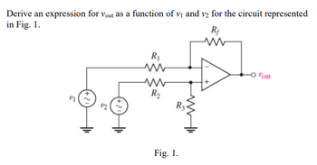
Transcribed Image Text:Derive an expression for Vout as a function of v₁ and v₂ for the circuit represented
in Fig. 1.
21
2/2
R₁
ww
R₂
R3
Fig. 1.
Rf
www
"out
Expert Solution
This question has been solved!
Explore an expertly crafted, step-by-step solution for a thorough understanding of key concepts.
This is a popular solution
Trending nowThis is a popular solution!
Step by stepSolved in 2 steps with 2 images

Knowledge Booster
Learn more about
Need a deep-dive on the concept behind this application? Look no further. Learn more about this topic, electrical-engineering and related others by exploring similar questions and additional content below.Similar questions
- II-The voltage and current at the terminals of the circuit element in Fig 1.5 are zero for t 0. V,t 20V and a) Find the time when the power delivered to the circuit element is maximum. b) Find the maximum value of power. c) Find the total energy delivered to the circuit element.arrow_forward1. (c) Determine V , RH, IN,and Ry at terminals 1-2 of the circuit in Fig.P1c. 62 e 1 01 24 V 60 VTH Figure P1(c) 2.arrow_forwardConnect the circuit as shown in Fig. below and record your data in table 3. SW2 Cin SWO SW1 B Table 3 10 SUM Lo Cout 8 Li INPUTS OUTPUTS Cin (SW2) B (SW1) A (SW0) Sum (Lo) Cout (L1) 0 0 0 0 0 1 0 1 0 0 1 1 1 0 0 1 0 1 1 1 0 1 1 1arrow_forward
- Current Dividers 1.1 lem 1.10 Current dividers play an important role in circuit design. (c) Therefore it is important to develop a facility for dealing with current dividers in circuit analysis. Figure P1.10 shows a two- resistor current divider fed with an ideal current source /. Show that R2 R+R2 3 V R R,+R2 and find the voltage / that develops across the current divider. Fig 1.15 find betw flow node R2 Figure P1.10arrow_forwardR₁ AS Vs R₂ VTH= R3 R4 RL RTH= VTH B Figure 1a) Simple circuit to be analyzed Figure 1b) Thevenin's equivalent of Fig. 1a) 1.- A simple Circuit. Determine the Thevenin's equivalent of the circuit given in fig. 1a). Consider the following values: R₁ = 24092, R2 = 2700, R3 = 56092, R4 = 1k2, and Vs = 10 V. Show all your calculations on your own handwritten. Indicate the units. RTH RL 23arrow_forwardPlease answer in typing format please ASAP for the like Ok please answer in typing format please ASAP for Please I will like it please thankarrow_forward
arrow_back_ios
arrow_forward_ios
Recommended textbooks for you
 Introductory Circuit Analysis (13th Edition)Electrical EngineeringISBN:9780133923605Author:Robert L. BoylestadPublisher:PEARSON
 Delmar's Standard Textbook Of ElectricityElectrical EngineeringISBN:9781337900348Author:Stephen L. HermanPublisher:Cengage Learning
 Programmable Logic ControllersElectrical EngineeringISBN:9780073373843Author:Frank D. PetruzellaPublisher:McGraw-Hill Education
 Fundamentals of Electric CircuitsElectrical EngineeringISBN:9780078028229Author:Charles K Alexander, Matthew SadikuPublisher:McGraw-Hill Education
 Electric Circuits. (11th Edition)Electrical EngineeringISBN:9780134746968Author:James W. Nilsson, Susan RiedelPublisher:PEARSON
 Engineering ElectromagneticsElectrical EngineeringISBN:9780078028151Author:Hayt, William H. (william Hart), Jr, BUCK, John A.Publisher:Mcgraw-hill Education,

Introductory Circuit Analysis (13th Edition)
Electrical Engineering
ISBN:9780133923605
Author:Robert L. Boylestad
Publisher:PEARSON

Delmar's Standard Textbook Of Electricity
Electrical Engineering
ISBN:9781337900348
Author:Stephen L. Herman
Publisher:Cengage Learning

Programmable Logic Controllers
Electrical Engineering
ISBN:9780073373843
Author:Frank D. Petruzella
Publisher:McGraw-Hill Education

Fundamentals of Electric Circuits
Electrical Engineering
ISBN:9780078028229
Author:Charles K Alexander, Matthew Sadiku
Publisher:McGraw-Hill Education

Electric Circuits. (11th Edition)
Electrical Engineering
ISBN:9780134746968
Author:James W. Nilsson, Susan Riedel
Publisher:PEARSON

Engineering Electromagnetics
Electrical Engineering
ISBN:9780078028151
Author:Hayt, William H. (william Hart), Jr, BUCK, John A.
Publisher:Mcgraw-hill Education,