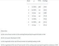
I only need help with part d.
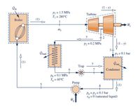
The figure below provides steady-state operating data for a cogeneration cycle that generates electricity and provides heat for campus buildings. Steam at 1.5 MPa, 280°C, enters a two-stage turbine with a mass flow rate of m1 = 2 kg/s. A fraction of the total flow, y = 0.15, is extracted between the two stages at 0.2 MPa to provide for building heating, and the remainder expands through the second stage to the condenser pressure of 0.1 bar. Condensate returns from the campus buildings at 0.1 MPa, 60°C and passes through a trap into the condenser, where it is reunited with the main feedwater flow. Saturated liquid leaves the condenser at 0.1 bar.


Trending nowThis is a popular solution!
Step by stepSolved in 2 steps with 3 images

- Fuel- Air Stack Combustion gases to stack Boiler Turbine Electric generator Condenser Warm water Feedwater pump De -Pump Makeup water Cooling tower Cooled water A chemical plant currently purchases 2.4 x 10⁵ MW.h of electricity annually from the local utility provider. An aging boiler in the local provider's facility provides 4 x 10⁸ kg of process steam at 20 bar. Consider the feasibility of a new system to meet the need of the steam and electricity. This system will use turbine to produce the electricity and a heat- recovery steam generator to produce the steam. Write a technical proposal for your proposed system.arrow_forward6. A 600-MW coal electric power plant substitutes 8% of its fuel with "tree clippings," which are tree branches that are cut to clear roads as well as the access lanes (rights of way) of power lines. The tree clippings are fed in the boiler together with the coal. How much coal is saved annually by this practice and how much CO₂ emissions are prevented?arrow_forwardA thermal power plant operates on a regenerative cycle with a single open feed water heater, as shown in the figure. For the state points shown, the specific enthalpies are h1 =2800 kJ/kg and h2 =200 kJ/kg. The bleed to the feed water heater is 20% of the boiler steam generation rate. The specific enthalpy at state 3 isarrow_forward
- 1. Consider the following schematic of a power plant (operating in what is called a 'Rankine Cycle') Turbine Steam generator Condenser Coling water Economiaer The power plant control room reports that the plant is operating continuously at the following peak load conditions: a. Power to pump = 300KW b. Rate of steam flow = 25 kg/s c. Cooling water temperature at condenser inlet = 13 C d. Cooling water temperature at condenser outlet = 34 C Additionally, the following measurements were made at various points in the piping connecting the power plant components Data Pressure Temp. Quality enthalpy Specific Velocity (kJ/kg) point (kPa) volume (m/s) (m3/kg) (C) (x) 1 6200 2 6100 43 5900 177 ---- 4. 5700 493 ----- 5 5500 482 ----- 6 103 0.94 183 7 96 43 -----arrow_forwardNeed help with this engineering problem.arrow_forwardpart a b and carrow_forward
- 2. An electrical power plant that uses the Rankine cycle has a pump to increase the water pressure and multiply it by 50. In addition, there is a boiler whose fuel has a calorific value of 35 MJ/kg. The water that enters the process has a temperature of 60 °C and is at atmospheric pressure. The steam that leaves the turbine has a quality of 70% and the work generated in the turbine is 300 MW. a. How much water is needed to run the plant? b. What is its efficiency?arrow_forwardQ2. A cogeneration steam power plant has been modified with introducing an open feedwater heater as shown in figure below. Working pressure of the plant is between 6 MPa and 10 kPa for the boiler pressure and condensate pressure. The steam is extracted at 0.5 MPa for process heater and feedwater heater. The superheated srteam enters the turbine at 500°C at a rate of 25 kg/s and expands to the condensate pressure of 0.5 MPa. There is 60 percent of the steam is extracted from the turbine at the pressure of 0.5 MPa, and the remainder expands to a pressure of 10 kPa. Part of the extracted steam is used to heat feedwater and the rest of the extracted steam is used for process heating. The steam leaves the process heater as a saturated liquid at 0.5 MPa. It is subsequently mixed with the feedwater leaving the feedwater heater, and the mixture is pumped to the boiler pressure. The steam in the condenser is cooled and condensed by the cooling water from a nearby river, which enters the…arrow_forwardBook - Advance Energy Systems, 2ed, Khartchenkoarrow_forward
 Elements Of ElectromagneticsMechanical EngineeringISBN:9780190698614Author:Sadiku, Matthew N. O.Publisher:Oxford University Press
 Mechanics of Materials (10th Edition)Mechanical EngineeringISBN:9780134319650Author:Russell C. HibbelerPublisher:PEARSON
 Thermodynamics: An Engineering ApproachMechanical EngineeringISBN:9781259822674Author:Yunus A. Cengel Dr., Michael A. BolesPublisher:McGraw-Hill Education
 Control Systems EngineeringMechanical EngineeringISBN:9781118170519Author:Norman S. NisePublisher:WILEY
 Mechanics of Materials (MindTap Course List)Mechanical EngineeringISBN:9781337093347Author:Barry J. Goodno, James M. GerePublisher:Cengage Learning
 Engineering Mechanics: StaticsMechanical EngineeringISBN:9781118807330Author:James L. Meriam, L. G. Kraige, J. N. BoltonPublisher:WILEY


