Introductory Circuit Analysis (13th Edition)
13th Edition
ISBN: 9780133923605
Author: Robert L. Boylestad
Publisher: PEARSON
expand_more
expand_more
format_list_bulleted
Concept explainers
Question
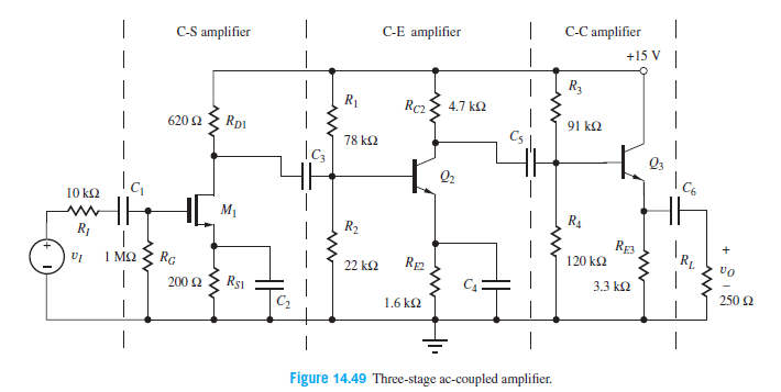
Estimate the gain of the amplifier shown using our simple design estimates if M1 has VGS − VTN = 1 V. What is the origin of the discrepancy?

Transcribed Image Text:C-S amplifier
C-E amplifier
C-C amplifier
+15 V
|
R3
R1
Rc2
4.7 k2
620 2
Rp1
91 k2
78 k2
Q3
10 k2
M1
R4
R2
R1
RE3
120 k2
1 M2
Rc
22 k2
RE2
3.3 k2
200 2
Rs1
250 2
1.6 k2
Figure 14.49 Three-stage ac-coupled amplifier.
Expert Solution
This question has been solved!
Explore an expertly crafted, step-by-step solution for a thorough understanding of key concepts.
This is a popular solution
Trending nowThis is a popular solution!
Step by stepSolved in 6 steps with 1 images

Knowledge Booster
Learn more about
Need a deep-dive on the concept behind this application? Look no further. Learn more about this topic, electrical-engineering and related others by exploring similar questions and additional content below.Similar questions
- Ql:A: Design a multi-range ammeter of 0.5 and I Amp. using a PMMC(galvanometer) of 500 internal resistance and full-scale current of 1 ma. Show the way of connection with the load RL.arrow_forwardSolve for the common base amplifier Given B= 100, Si=0.7 (voltage drop) Find a) Avs b) Ais c). What are Ac voltage at each point indicated (A,B,C,D,E) in the circuit with Vs = 100mVp-parrow_forwardYou are tasked with designing a linear amplifier using an NPN BJT for the circuit shown below. This means the transistor iv curves apply here. The voltages given are Vcc = 14 V and Vs = 1.0 V. The datasheet for the transistor says VBE (ON) = 0.7 V,VCE (SAT) = 0.2 V, and ß = 400. The design should have ic = 12 mA and VCE = 8 V. Find the resistances Rb and Rc that give the required ic and VCE. Vs H Rb M d VBE Rc VCE Vccarrow_forward
- 4. Is it possible to get a gain less than unity using a non-inverting amplifier configuration? If yes, sketch a circuit.arrow_forwardQuestion 7) Design a JFET amplifier network with ldss-8 mA, Ve=-4 V, R1=110 MN, R2=10 MQ. When an input AC signal V=10 mV is applied to the network, an output signal Vo=2V AC is obtained. (suppose that ra2 10R0) a) Draw the JFET amplifier network you prefer to design, and explain why you choose this network b) Explain the aims and reasons in using of all the peripheral components handled on your network c) Draw AC equivalent re model of the network (5p.) d) Draw transfer characteristic curve and derive lda and Vasa values from the characteristic curve e) Calculate Av, gm, VoD, Ro, Rs, Z; and Zn. Note: Please, do not forget using resistors and capacitors as peripheral elements whatever required for your complete design in the question (i.e. input, output terminals etc.)arrow_forwardFor amplifier design, consider a very large load resistance RL . Use a 15 V DC source and a sinusoidal input signal of 200 mVpp and 1 kHz. Hint: you can start by choosing a collector (Icq) or drain (IDQ) operating current between 5 mA and 10 mA. 1. Design an input stage with a common drain amplifier that complies with thefollowing specifications: Voltage gain greater than or equal to 1 (Av1 ≥ 1). Input impedance greater than or equal to 250 kΩ (Zi1 ≥ 250 kΩ). Output impedance less than or equal to 2 kΩ (Zo1 ≤ 2 kΩ). Low cut frequency less than or equal to 20 Hz (fcb1 ≤ 20 kHz). Use a 2N3819 (NTE312) transistor.arrow_forward
- VoD +12 V For the circuit of the adjacent figure a) Given that Ip = 2.83 mA, VGS(om=-7 V and Ipss = 8 mA , find VDs and VGs.. b) If a 50 mV rms input signal is applied to the amplifier, what is the peak-to-peak output voltage? gm = 5000 µS. c) Calculate the output resistance. %3D Ro 10AF 0.1 uF R 10 L. Ra 10 MA 10kn ID= 2.83 mA, Vas (Oef)=-7V. %3Darrow_forwardWhat is mean by operational amplifier? Derive the input/output relationship in inverting and non-inverting amplifier.arrow_forwardPlease solve with steps, using to study. Will upvote!arrow_forward
arrow_back_ios
arrow_forward_ios
Recommended textbooks for you
 Introductory Circuit Analysis (13th Edition)Electrical EngineeringISBN:9780133923605Author:Robert L. BoylestadPublisher:PEARSON
 Delmar's Standard Textbook Of ElectricityElectrical EngineeringISBN:9781337900348Author:Stephen L. HermanPublisher:Cengage Learning
 Programmable Logic ControllersElectrical EngineeringISBN:9780073373843Author:Frank D. PetruzellaPublisher:McGraw-Hill Education
 Fundamentals of Electric CircuitsElectrical EngineeringISBN:9780078028229Author:Charles K Alexander, Matthew SadikuPublisher:McGraw-Hill Education
 Electric Circuits. (11th Edition)Electrical EngineeringISBN:9780134746968Author:James W. Nilsson, Susan RiedelPublisher:PEARSON
 Engineering ElectromagneticsElectrical EngineeringISBN:9780078028151Author:Hayt, William H. (william Hart), Jr, BUCK, John A.Publisher:Mcgraw-hill Education,

Introductory Circuit Analysis (13th Edition)
Electrical Engineering
ISBN:9780133923605
Author:Robert L. Boylestad
Publisher:PEARSON

Delmar's Standard Textbook Of Electricity
Electrical Engineering
ISBN:9781337900348
Author:Stephen L. Herman
Publisher:Cengage Learning

Programmable Logic Controllers
Electrical Engineering
ISBN:9780073373843
Author:Frank D. Petruzella
Publisher:McGraw-Hill Education

Fundamentals of Electric Circuits
Electrical Engineering
ISBN:9780078028229
Author:Charles K Alexander, Matthew Sadiku
Publisher:McGraw-Hill Education

Electric Circuits. (11th Edition)
Electrical Engineering
ISBN:9780134746968
Author:James W. Nilsson, Susan Riedel
Publisher:PEARSON

Engineering Electromagnetics
Electrical Engineering
ISBN:9780078028151
Author:Hayt, William H. (william Hart), Jr, BUCK, John A.
Publisher:Mcgraw-hill Education,