
Introductory Circuit Analysis (13th Edition)
13th Edition
ISBN: 9780133923605
Author: Robert L. Boylestad
Publisher: PEARSON
expand_more
expand_more
format_list_bulleted
Related questions
Question
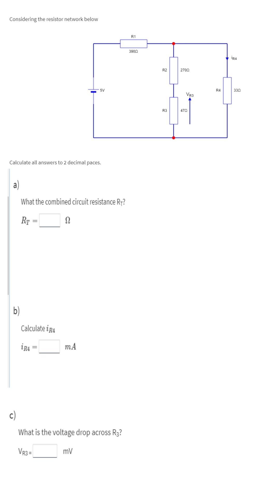

Transcribed Image Text:Considering the resistor network below
R1
3900
R2
2700
5V
R4
330
VR3
R3
470
Calculate all answers to 2 decimal paces.
a)
What the combined circuit resistance R7?
RT :
b)
Calculate iR4
ir
mA
c)
What is the voltage drop across R3?
VR3 =
mV
Expert Solution
This question has been solved!
Explore an expertly crafted, step-by-step solution for a thorough understanding of key concepts.

This is a popular solution

Trending nowThis is a popular solution!

Step by stepSolved in 5 steps with 10 images

Knowledge Booster

Similar questions
- Based upon the following assumptions: V1 = 13V, V2 = 19V, R1 = 0.9kQ, R2 = 9300, R3 = 3kQ, R4 = 3.4kQ, R5 = 1.2k2. If R5 is the load resistor find VTH Answer in volts with 3 significant digits, only enter the number, don't enter the units. V1 V2arrow_forwardConsider the circuit shown in the figure below. R₁ = R2= 11.00 and R3 =R4= 5.00 2 and Rs 20 Ω. a. Color code and reduce the circuit section to one equivalent resistor. Show each step and combine the resistors SYMBOLLICALLY before plugging in any numbers. W R4 a R1 W R2 W R3 W 25.0 V b. Find the potential difference between points a and b. b C. Find the current in the R5. W R5arrow_forwardNeeds Complete typed solution with 100 % accuracy.arrow_forward
arrow_back_ios
arrow_forward_ios
Recommended textbooks for you
- Introductory Circuit Analysis (13th Edition)Electrical EngineeringISBN:9780133923605Author:Robert L. BoylestadPublisher:PEARSON
 Delmar's Standard Textbook Of ElectricityElectrical EngineeringISBN:9781337900348Author:Stephen L. HermanPublisher:Cengage Learning
 Programmable Logic ControllersElectrical EngineeringISBN:9780073373843Author:Frank D. PetruzellaPublisher:McGraw-Hill Education
  Fundamentals of Electric CircuitsElectrical EngineeringISBN:9780078028229Author:Charles K Alexander, Matthew SadikuPublisher:McGraw-Hill Education
 Electric Circuits. (11th Edition)Electrical EngineeringISBN:9780134746968Author:James W. Nilsson, Susan RiedelPublisher:PEARSON
 Engineering ElectromagneticsElectrical EngineeringISBN:9780078028151Author:Hayt, William H. (william Hart), Jr, BUCK, John A.Publisher:Mcgraw-hill Education,
Introductory Circuit Analysis (13th Edition)
Electrical Engineering
ISBN:9780133923605
Author:Robert L. Boylestad
Publisher:PEARSON
Delmar's Standard Textbook Of Electricity
Electrical Engineering
ISBN:9781337900348
Author:Stephen L. Herman
Publisher:Cengage Learning
Programmable Logic Controllers
Electrical Engineering
ISBN:9780073373843
Author:Frank D. Petruzella
Publisher:McGraw-Hill Education
Fundamentals of Electric Circuits
Electrical Engineering
ISBN:9780078028229
Author:Charles K Alexander, Matthew Sadiku
Publisher:McGraw-Hill Education
Electric Circuits. (11th Edition)
Electrical Engineering
ISBN:9780134746968
Author:James W. Nilsson, Susan Riedel
Publisher:PEARSON
Engineering Electromagnetics
Electrical Engineering
ISBN:9780078028151
Author:Hayt, William H. (william Hart), Jr, BUCK, John A.
Publisher:Mcgraw-hill Education,