
Introductory Circuit Analysis (13th Edition)
13th Edition
ISBN: 9780133923605
Author: Robert L. Boylestad
Publisher: PEARSON
expand_more
expand_more
format_list_bulleted
Related questions
Concept explainers
Question

Transcribed Image Text:## Problem 3.14
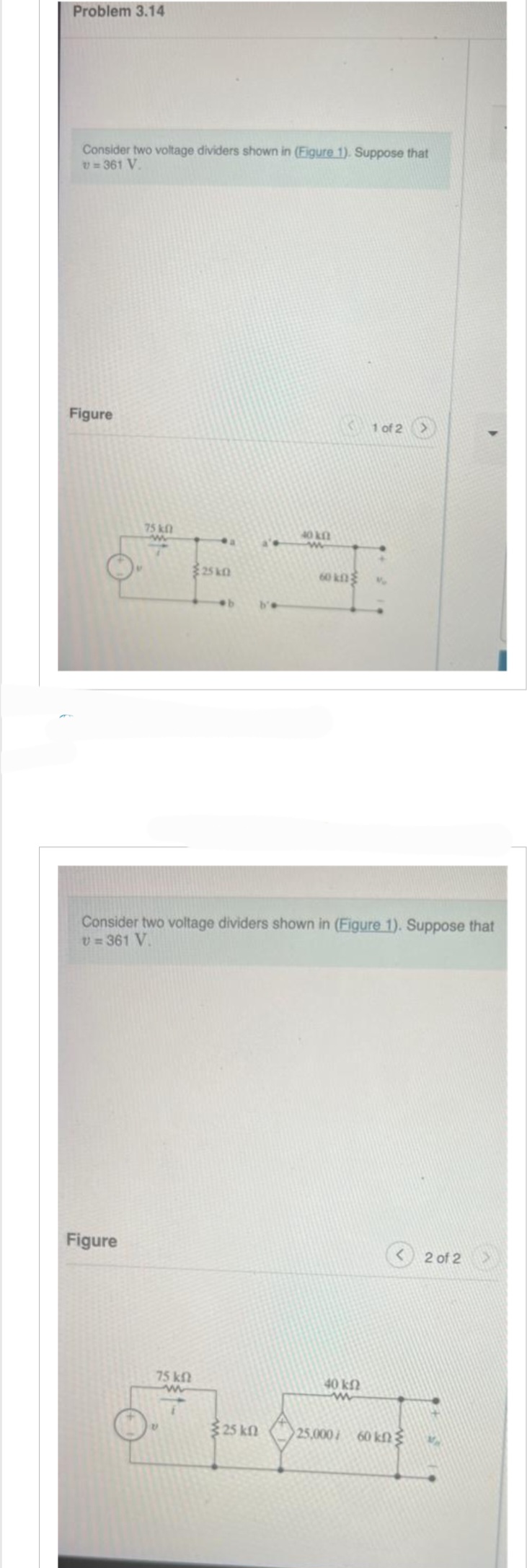
Consider two voltage dividers shown in **Figure 1**. Suppose that \( v = 361 \, \text{V} \).
### Figure Description
**Figure 1 of 2:**
- The circuit on the left consists of:
- A voltage source labeled \( v \).
- A series resistor of \( 75 \, \text{k}\Omega \) connected to node \( a \).
- Another series resistor of \( 25 \, \text{k}\Omega \) connected to node \( b \).
- The circuit on the right consists of:
- A series resistor of \( 40 \, \text{k}\Omega \) connected to node \( a' \).
- Another series resistor of \( 60 \, \text{k}\Omega \) connected to node \( b' \).
**Figure 2 of 2:**
- The combined circuit:
- A voltage source labeled \( v = 361 \, \text{V} \).
- A series resistor of \( 75 \, \text{k}\Omega \).
- A series resistor of \( 25 \, \text{k}\Omega \).
- A voltage-dependent voltage source with a gain of \( 25,000 \, io \).
- Resistors of \( 40 \, \text{k}\Omega \) and \( 60 \, \text{k}\Omega \) connected in series after the voltage-dependent source.
### Explanation
These figures illustrate the concept of voltage division using series resistors in a circuit. The second figure introduces a voltage-dependent source, showcasing advanced circuit analysis techniques. The problem requires analyzing these configurations with a given voltage source value to determine various parameters in the circuits.
![**Part A**
The voltage divider shown to the left in (Figure 1) is loaded with the voltage divider shown to the right in (Figure 1); that is, \( a \) is connected to \( a' \), and \( b \) is connected to \( b' \). Find \( v_0 \).
**Express your answer to three significant figures and include the appropriate units.**
\( v_0 = \) [Input box for Value] [Input box for Units]
[Submit Button] [Request Answer Button]
---
**Part B**
Now assume the voltage divider to the right is connected to the voltage divider to the left by means of a current-controlled voltage source as shown in (Figure 2). Find \( v_0 \).
**Express your answer to three significant figures and include the appropriate units.**
\( v_0 = \) [Input box for Value] [Input box for Units]
[Submit Button] [Request Answer Button]](https://content.bartleby.com/qna-images/question/27d05195-d4e5-49f1-8dc4-61bbc8dbf8a7/a8f16087-929b-4edc-a65e-eb7ed985d3b9/gvkzb0m_processed.jpeg)
Transcribed Image Text:**Part A**
The voltage divider shown to the left in (Figure 1) is loaded with the voltage divider shown to the right in (Figure 1); that is, \( a \) is connected to \( a' \), and \( b \) is connected to \( b' \). Find \( v_0 \).
**Express your answer to three significant figures and include the appropriate units.**
\( v_0 = \) [Input box for Value] [Input box for Units]
[Submit Button] [Request Answer Button]
---
**Part B**
Now assume the voltage divider to the right is connected to the voltage divider to the left by means of a current-controlled voltage source as shown in (Figure 2). Find \( v_0 \).
**Express your answer to three significant figures and include the appropriate units.**
\( v_0 = \) [Input box for Value] [Input box for Units]
[Submit Button] [Request Answer Button]
Expert Solution
This question has been solved!
Explore an expertly crafted, step-by-step solution for a thorough understanding of key concepts.

Step by stepSolved in 3 steps with 2 images

Knowledge Booster


Learn more about
Need a deep-dive on the concept behind this application? Look no further. Learn more about this topic, electrical-engineering and related others by exploring similar questions and additional content below.Similar questions
- Hello, I really need help with part A, part B,part C and part d because I have tried this problem multiple times and I keep getting the wrong answer so there any way you can help me with the problems and can you label them as wellarrow_forwardDetermine the currents and powers i1, i2, i3 and i4 in the figure.arrow_forwardHow would you improve this circuit? Draw a diagramarrow_forward
arrow_back_ios
arrow_forward_ios
Recommended textbooks for you
- Introductory Circuit Analysis (13th Edition)Electrical EngineeringISBN:9780133923605Author:Robert L. BoylestadPublisher:PEARSON
 Delmar's Standard Textbook Of ElectricityElectrical EngineeringISBN:9781337900348Author:Stephen L. HermanPublisher:Cengage Learning
 Programmable Logic ControllersElectrical EngineeringISBN:9780073373843Author:Frank D. PetruzellaPublisher:McGraw-Hill Education
  Fundamentals of Electric CircuitsElectrical EngineeringISBN:9780078028229Author:Charles K Alexander, Matthew SadikuPublisher:McGraw-Hill Education
 Electric Circuits. (11th Edition)Electrical EngineeringISBN:9780134746968Author:James W. Nilsson, Susan RiedelPublisher:PEARSON
 Engineering ElectromagneticsElectrical EngineeringISBN:9780078028151Author:Hayt, William H. (william Hart), Jr, BUCK, John A.Publisher:Mcgraw-hill Education,
Introductory Circuit Analysis (13th Edition)
Electrical Engineering
ISBN:9780133923605
Author:Robert L. Boylestad
Publisher:PEARSON
Delmar's Standard Textbook Of Electricity
Electrical Engineering
ISBN:9781337900348
Author:Stephen L. Herman
Publisher:Cengage Learning
Programmable Logic Controllers
Electrical Engineering
ISBN:9780073373843
Author:Frank D. Petruzella
Publisher:McGraw-Hill Education
Fundamentals of Electric Circuits
Electrical Engineering
ISBN:9780078028229
Author:Charles K Alexander, Matthew Sadiku
Publisher:McGraw-Hill Education
Electric Circuits. (11th Edition)
Electrical Engineering
ISBN:9780134746968
Author:James W. Nilsson, Susan Riedel
Publisher:PEARSON
Engineering Electromagnetics
Electrical Engineering
ISBN:9780078028151
Author:Hayt, William H. (william Hart), Jr, BUCK, John A.
Publisher:Mcgraw-hill Education,