
Introductory Circuit Analysis (13th Edition)
13th Edition
ISBN: 9780133923605
Author: Robert L. Boylestad
Publisher: PEARSON
expand_more
expand_more
format_list_bulleted
Related questions
Question
I need help with this problem and an explanation of the solution for the image described below. (Introduction to Signals and Systems)
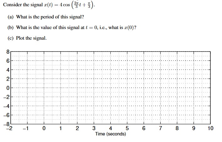

Transcribed Image Text:Consider the signal .x(t) = 4 cos (+3).
(a) What is the period of this signal?
(b) What is the value of this signal at t = 0, i.e., what is r(0)?
8
(c) Plot the signal.
co
6
4
2
0
-2
-4
-6
1
-2
-1
0
1
2
3
4
Time (seconds)
5
сл
CO
6
7
8
9
10
SAVE
AI-Generated Solution
info
AI-generated content may present inaccurate or offensive content that does not represent bartleby’s views.
Unlock instant AI solutions
Tap the button
to generate a solution
to generate a solution
Click the button to generate
a solution
a solution
Knowledge Booster

Similar questions
- Why this happening to my circuit? I am inputting a 0-3.3 V sine wave into my voltage follower circuit using NE5532P. At the output I am seeing 0-3.3 V sine wave as expected. However, when I add a 1000 uF capacitor and a loudspeaker to listen to the sine wave my wave is clipped and its reading -800 mV for min and +680 mV for max on the oscilloscope. How do I fix this so that I only listen to 0-3.3 V sine wave? I'm in the lab and this is confusing to me.arrow_forwardDerive an expression for Vout as a function of Vin, where Vin is the nodes connected to the Waveform Generator signal. Show your equations below, either typed or a picture of your handwritten work.arrow_forwardIn electronics, a clipper is a circuit designed to prevent a signal from exceeding a predetermined reference voltage level. A clipper does not distort the remaining part of the applied waveform. Clipping circuits are used to select, for purposes of transmission, that part of a signal waveform which lies above or below the predetermined reference voltage level. A biased clipper comes in handy when a small portion of positive or negative half cycles of the signal voltage is to be removed. ... Thus a biased negative clipper removes input voltage when the input signal voltage becomes greater than the battery voltage. QUESTION: Where do we exactly need to use a clipper circuit? State at least 3 examples and why it's needed on that application or device.arrow_forward
- Find period (divisions) and lag distance (Divisions)arrow_forwardThe carrier frequency is 600 Hz, and the modulating signal is a single-tone sinusoidal signal. The x-axis is in time while the y- axis is the amplitude of the AM signal. Determine the type of AM signal in the figure. 2 1.5 0.5 0.5 -1 -1.5 -2 0.005 0.01 0.015 0.02 0.025 0.03 0.035 0.04 0.045 0.05 Time (s) a. DSBFC b. DSBSC c. SSBSC d. VSBarrow_forwardSolve 16arrow_forward
- 229. If a periodic signal is decomposed into five sine waves with frequencies of 100, 300, 500, 700, and 900 Hz, what is its bandwidth? a. 2500 Hz b. 900 Hz c. 800 Hz d. can’t be determined with the information givenarrow_forwardplease show work. i will give your work a thumbs up 7. Consider the oscilloscope screen shot below: ek Run 4.00p 1.0000 Vpp 0.000000 1. 5.000S/ IM points 500mV AFG Sine 100.00 Hz 0.00 V As shown the Volt / Div - 500mV per division, Time Base - 4.00 us per division, and Frequency is 100 KHz: a) Determine the peak-to-peak voltage (Vpp) and half-cycle average voltage (Vave). b) Determine the peak-voltage (Vpk) and root-mean-square voltage (Vrms). c) What is the period (T) of the IMHZ signal?arrow_forwardPlease show how to solve this.arrow_forward
- Sequential Circuits, Thank you in advance for your answer.arrow_forwardio T1 T3 + Vs iş Vo RL load F.W.D T2 T4 H.W Find the Fourier series of the supply current of 1. Fully controlled bridge rectifier 2. Semi-controlled bridge rectifierarrow_forward18. What waveform can be measured at the ouput uO of the signal generator shown below? Sine waveSawtooth waveSquare waveTriangle wavearrow_forward
arrow_back_ios
SEE MORE QUESTIONS
arrow_forward_ios
Recommended textbooks for you
- Introductory Circuit Analysis (13th Edition)Electrical EngineeringISBN:9780133923605Author:Robert L. BoylestadPublisher:PEARSON
 Delmar's Standard Textbook Of ElectricityElectrical EngineeringISBN:9781337900348Author:Stephen L. HermanPublisher:Cengage Learning
 Programmable Logic ControllersElectrical EngineeringISBN:9780073373843Author:Frank D. PetruzellaPublisher:McGraw-Hill Education
  Fundamentals of Electric CircuitsElectrical EngineeringISBN:9780078028229Author:Charles K Alexander, Matthew SadikuPublisher:McGraw-Hill Education
 Electric Circuits. (11th Edition)Electrical EngineeringISBN:9780134746968Author:James W. Nilsson, Susan RiedelPublisher:PEARSON
 Engineering ElectromagneticsElectrical EngineeringISBN:9780078028151Author:Hayt, William H. (william Hart), Jr, BUCK, John A.Publisher:Mcgraw-hill Education,
Introductory Circuit Analysis (13th Edition)
Electrical Engineering
ISBN:9780133923605
Author:Robert L. Boylestad
Publisher:PEARSON
Delmar's Standard Textbook Of Electricity
Electrical Engineering
ISBN:9781337900348
Author:Stephen L. Herman
Publisher:Cengage Learning
Programmable Logic Controllers
Electrical Engineering
ISBN:9780073373843
Author:Frank D. Petruzella
Publisher:McGraw-Hill Education
Fundamentals of Electric Circuits
Electrical Engineering
ISBN:9780078028229
Author:Charles K Alexander, Matthew Sadiku
Publisher:McGraw-Hill Education
Electric Circuits. (11th Edition)
Electrical Engineering
ISBN:9780134746968
Author:James W. Nilsson, Susan Riedel
Publisher:PEARSON
Engineering Electromagnetics
Electrical Engineering
ISBN:9780078028151
Author:Hayt, William H. (william Hart), Jr, BUCK, John A.
Publisher:Mcgraw-hill Education,