
Delmar's Standard Textbook Of Electricity
7th Edition
ISBN: 9781337900348
Author: Stephen L. Herman
Publisher: Cengage Learning
expand_more
expand_more
format_list_bulleted
Related questions
Question
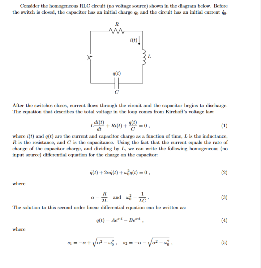

Transcribed Image Text:Consider the homogeneous RLC circuit (no voltage source) shown in the diagram below. Before
the switch is closed, the capacitor has an initial charge go and the circuit has an initial current go.
R
w
i(t)
q(t)
C
н
After the switches closes, current flows through the circuit and the capacitor begins to discharge.
The equation that describes the total voltage in the loop comes from Kirchoff's voltage law:
di(t)
L
+ Ri(t) + (t) = 0,
dt
(1)
where i(t) and q(t) are the current and capacitor charge as a function of time, L is the inductance,
R is the resistance, and C is the capacitance. Using the fact that the current equals the rate of
change of the capacitor charge, and dividing by L, we can write the following homogeneous (no
input source) differential equation for the charge on the capacitor:
ä(t)+2ag(t)+wg(t) = 0,
(2)
where
R
a
2L
and w₁ = C
LC
The solution to this second order linear differential equation can be written as:
where
81=
q(t) = Ae³¹- Bel
82 =
(3)
(4)
(5)

Transcribed Image Text:($1+20)90 +90
(82 +20)90 +90
and B
81-82
81-82
(6)
1. (6 marks) Show that the solution for q(t) from equation (4) satisfies the homogenous differ-
ential equation for the RLC circuit with no voltage source from equation (2).
2. (5 marks) Write a MATLAB function to evaluate q(t), ġ(t), and ä(t) from time t = 0 tot - T
in steps of AT. The equation for q(t) describes the charge on the capacitor as a function of
time, q(t) describes the current in the circuit, and ä(t) describes the rate of change of the
current.
Note that s₁ and s₂ can be complex numbers, depending on the values of a and up. MATLAB
automatically handles the computation of complex numbers.
A function template can be found in the file HomogeneousRLC.m, which takes as input the
resistance, inductance, and capacitance of the circuit, the initial charge on the capacitor, the
initial current in the circuit, the time step, and the final time.
3. Using the MATLAB function that you wrote in the previous question, calculate the voltage
drop across each component in the RLC circuit, and the energy stored in each of the inductor
and capacitor. Use a value of zero for the initial current go, and chose the initial charge on
the capacitor go so that the initial voltage on the capacitor is 1V. The time scale will need
to be chosen carefully so that the entire output is clearly visible.
You may need to look up some simple formulas to calculate these voltages and energies, but
the important pieces of information - the charge on the capacitor, the current, and the rate
of change of the current - are all provided by the function from the previous question.
(a) (10 marks) Choose realistic values of R, L, and C such that a> wp and make a graph
that shows the voltage drop across the resistor, inductor, and capacitor, and the sum of
all three, as a function time. Make another graph that shows the energy stored in each
of the inductor and capacitor, and the total energy stored, as a function of time.
(b) (10 marks) Choose values of R, L, and C such that a <wo and make another pair of
graphs as before that show the voltages and energies in the RLC circuit as a function of
time. Label the R, L, C, and go values on each graph.
4. (4 marks) A special case occurs when a wo, which results in 81-82. Equation (4) cannot
be evaluated directly if s₁ = 82 since q(t). If L'Hospital's rule is applied as s₁→ 82 then
where
q(t) que+(ago + ġo) teat
R
81-82-0 and at
2L
(7)
(8)
Modify the MATLAB function that you wrote to check for the condition a = wo (or equiva-
lently, $1 =82) and calculate q(t), q(t), and ä(t) accordingly.
Submit the MATLAB code for your function as a .m file.
Expert Solution
This question has been solved!
Explore an expertly crafted, step-by-step solution for a thorough understanding of key concepts.

Step by stepSolved in 2 steps with 1 images

Knowledge Booster

Similar questions
- A 15-F AC capacitor is connected in series with a 50 resistor. The capacitor has a voltage rating of 600 WVDC. The capacitor and resistor are connected to a 480-V, 60-Hz circuit. Is the voltage rating of the capacitor sufficient for this connection?arrow_forwardYou are an electrician working in an industrial plant. You discover that the problem with a certain machine is a defective capacitor. The capacitor is connected to a 240-volt AC circuit. The information on the capacitor reveals that it has a capacitance value of 10 mF and a voltage rating of 240 VAC. The only 10-mF AC capacitor in the storeroom is marked with a voltage rating of 350 WVDC. Can this capacitor be used to replace the defective capacitor? Explain your answer.arrow_forwardThree capacitors having capacitance values of 20F,40F, and 50F are connected in parallel to a 60 - Hz power line. An ammeter indicates a circuit current of 8.6 amperes. How much current is flowing through the 40F capacitor?arrow_forward
- Pls. write solution neatlyarrow_forwardThe figure below shows a simple RC circuit with a 3.30-μF capacitor, a 4.40-M resistor, a 9.00-V emf, and a switch. What are the following exactly 9.00 s after the switch is closed? (a) the charge on the capacitor 13.7204 UC (b) the current in the resistor 0.0110522 x Your response is off by a multiple of ten. HA (c) the rate at which the capacitor is storing energy μW (d) the rate at which the battery is delivering energy μWarrow_forwardUsing the series circuit in Figure 3 consisting of a voltage source V, the resistor R and the fully uncharged capacitor C, how to find the value of the capacitance C considering as known data the time constant of the circuit T and the value of the resistor R? V ww Rarrow_forward
- 1. A purely resistive circuit the current is leading by 90° with respect to voltage. 2. A purely inductive circuit the current is lag behind the voltage by 90°. 3. A purely capacitive circuit the current is lead by 90° with respect to the voltage. 4. A capacitor element stored magnetic energy. 5. An inductor element stored electrical energy. 6. Resistor elements consume power. 7. Angle between current and voltage is called power. 8. The power factor angle for a purely resistive is zero. 9. The power factor angle for a purely inductive load is -90°. 10. The power factor of a purely capacitive is leading.arrow_forwardLet's say you measure t1/2 to be 0.037 seconds and the resistance in the circuit is 68 Ohms. Then what is the capacitance in micro Farads? Answer in micro Farads.arrow_forwardA 20-µF (C1) and a 40-µF (C2) capacitor are connected in parallel to a 480-V, 60-Hz source. What is the inductive reactance and current flow through C1? What is the inductive reactance and current flow through C2?arrow_forward
- The following figure represents an RC-Circuit with the switch. In Figure A, the capacitor is initially uncharged. In Figure B, the capacitor is initially fully charged. 1) Draw and label the current direction immediately after the switch is closed for each figure. 2) Consider Figure A. What is the voltage across the capacitor as t → 0? Explain. 3) Consider Figure B. Is the voltage across the resistor increasing, decreasing or staying the same as t → 0? Explain. A) B) R Carrow_forwardAt 0-, no currrent flows through the capacitors because they are open, how did you combine the capacitors for the voltage divider since it is the capacitance value and not reactance, is it right? Can we just combine the capacitance value? Please explain. I did not understand..arrow_forwardAsap plzzzarrow_forward
arrow_back_ios
SEE MORE QUESTIONS
arrow_forward_ios
Recommended textbooks for you
- Delmar's Standard Textbook Of ElectricityElectrical EngineeringISBN:9781337900348Author:Stephen L. HermanPublisher:Cengage Learning
Delmar's Standard Textbook Of Electricity
Electrical Engineering
ISBN:9781337900348
Author:Stephen L. Herman
Publisher:Cengage Learning