Database System Concepts
7th Edition
ISBN: 9780078022159
Author: Abraham Silberschatz Professor, Henry F. Korth, S. Sudarshan
Publisher: McGraw-Hill Education
expand_more
expand_more
format_list_bulleted
Question
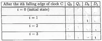
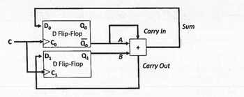
3(a): Consider the following circuit, which uses two D flip-flops with falling edge triggers along with -bit full adder. The flip-flops are controlled by a single clock, C.
Suppose C, Q0 and Q1 all initially have the value 0.
- First, fill in the blanks in the "i " = 0 (initial state)" row to show the values of D0 and D1 at this initial time (assume the results of the adder have had time to stabilize) .
- Next, show the values of Q0 , Q1, D0 , and D1 once they have stabilized after the ith falling edge of the clock, where i ranges from 1 to 4. Note that both the A and Carry In inputs of the adder are (Q not ) Q'0 not Q0
- None of these first four rows should be the exactly the same.

Transcribed Image Text:After the ith falling edge of clock C QoQ₁ Do D₁
i = 0 (initial state)
i = 1
i
2 =
2
3

Transcribed Image Text:Do
с
Ti
Qo
D Flip-Flop
PS
Q₂
Q₁
D Flip-Flop
A
B
+
Carry In
Carry Out
Sum
Expert Solution
This question has been solved!
Explore an expertly crafted, step-by-step solution for a thorough understanding of key concepts.
This is a popular solution
Trending nowThis is a popular solution!
Step by stepSolved in 6 steps

Knowledge Booster
Learn more about
Need a deep-dive on the concept behind this application? Look no further. Learn more about this topic, computer-science and related others by exploring similar questions and additional content below.Similar questions
- Please draw wave form according to equations at the top of the page. A truth table might also help me to understand. Thank you.arrow_forwardDesign a code converter that converts an unsigned number a into its negative 2's complement representation -a. Specifically, the circuit has two inputs: a1 and ao, and three outputs: b1 and bo (the equivalent to -a) and valid, which is 1 when -a can be represented in 2's complement and O otherwise. 1. Write the truth table for the code converter. 2. Give the simplest SOP expressions for the functions b1, bo, and valid.arrow_forwardGiven is the following circuit with 4 inputs A, B, C, D and the output Y. (O denotes an inverter.) ABCD & 00 & & & =1 & & =1 & & & ≥1 Y a) Create the truth table for this circuit. b) Use a K-map to simplify this circuit. c) State a Boolean equation that describes Y based on your simplification.arrow_forward
- Modify the VHDL code in Figure 7.52 by adding a parameter that sets the number of flip-flops in the counter. LIBRARY ieee; USE ieee.std logic_1164.all; USE ieee.std logic.unsigned.all; ENTITY upcount IS PORT ( Clock, Resetn, E IN Q END upcount; STD LOGIC ; : OUT STD_LOGIC_VECTOR (3 DOWNTO 0)) ; ARCHITECTURE Behavior OF upcount IS SIGNAL Count : STD LOGIC_VECTOR (3 DOWNTO 0) ; BEGIN PROCESS ( Clock, Resetn ) BEGIN IF Resetn = '0' THEN Count <= "0000" ; ELSIF (Clock’EVENT AND Clock = '1') THEN IF E = '1' THEN Count <= Count + 1 ; ELSE Count <= Count; END IF ; END IF; END PROCESS; Q <= Count ; END Behavior ; Figure 7.52 ode for a four-bit up-counter.arrow_forward3. Below is the characteristic table for a "GP" flip-flop (it doesn't really exist; I just made it up). Q+ 1 G 0 0 1 1 a. P 0 1 0 Q Q 0 Give the excitation table for this flip-flop. b. Suppose we wanted to implement the serial adder we developed in class using a GP flip-flop, give the equations necessary for the G and P inputs.arrow_forwardHardware & Architecture HW #5 - 100 Pts 6. a. (8 Pts) Label the Boolean output of each gate. Note: The labels you need are giving in the Table for Part b; you only need to map each to the correct location in the circuit. b. Using the table provided, derive a Truth Table for the Output B Inputs (3 Pts) D 3 Pts 2 Pts 3 Pts 3 Pts 2 Pts 3 Pts. A B C D A A+B T BC 3 Pts C+D A+ B+ BC (A + B)(C + D) 0 0 0 0 00 0 1 0 0 1 0 0 0 1 1 O 1 0 0 0 1 0 1 0 1 1 0 0 1 1 1 1 00 0 1 0 0 1 1 0 1 0 0 1 1 1 1 00 1 0 1 1 1 1 0 1 1 1 3 Pts A+B+BC+(A + B) (C + D)arrow_forward
- The following circuit implements a state machine. Obtain its state table and state diagram. (You need to show all the steps). D Q CLK CLK reset resetarrow_forwardA hidden passage is controlled by a redstone circuit for an adder which performs binary addition two bits at a time. He notes that it adds the inputs (x2i, y21) and (x2i+1, Y2i-1), the (2i)th and (2i+1)th bits of two binary numbers, and returns the sum as outputs s2i, S2+1. The addition is performed each clock cycle, starting from i = 0 until i = п 1, where n is the number of bits and 2 presumed to be even. For example, when adding x = 011010, and y number as x1:0 and y1:0 respectively. In this case, X1:0 is 10 and y1:0 = 01, and the carry bit co is 1. Our sum, s,0 is 00 and the next carry bit c, is 1. On the next clock cycle, we look at the next two 0110012, we take the first two bits of each bits, X3:2 = 10 and y3:2 = 10, so our sum s3-2 is 01, but we have a carry c4 1. Finally, our last addition to perform is on X5-4 = 01 and y5:4 = 01, with a carry bit c4 = 1. Our sum therefore is s54 = 11 with carry C6 = 0. Our final result of the addition is 1101002. You are only responsible for…arrow_forward5. Find the Boolean expression for the following circuit, and simplify it. SHOW YOUR WORK. A Вarrow_forward
- 2. Design a combinational circuit with three inputs, x, y, and z, and three outputs, A, B, and C. When the binary input represents any of the decimal digits 1, 2, 3, or 6, the binary output should represent the decimal digit that is one greater than the input, that is 2, 3, 4 and 7, respectively. Similarly, when the binary input represents any of the digits 4, or 7, the binary output should represent the digit that is two less than the input. The remaining two inputs, that are the binary representations of the decimal digits 0 and 5 never occur. Draw the truth table, and give all the minimal forms for the functions that represent the outputs A, B, and C. Uarrow_forwardThe following state table represents a sequential circuit with two T flip-flops A and B and one input x and one output y. i- Insert the values of; TA, TB and the current state output y(t), if y(t)=[A'(t)+B`(t)]L 1. use the highlighted cells for your answers; Excitation table for T-flip flop Q(t) Q(t+1) 1 1 1 1 1 1 DEC A(t) B(t) A(t+1) B(t+1) TA TB y(t) 1 1 1 1 1 1 1 2 1 1 3 1 1 41 1 0. 1 1 1 1 1 7 1 1 1arrow_forward
arrow_back_ios
arrow_forward_ios
Recommended textbooks for you
 Database System ConceptsComputer ScienceISBN:9780078022159Author:Abraham Silberschatz Professor, Henry F. Korth, S. SudarshanPublisher:McGraw-Hill Education
 Starting Out with Python (4th Edition)Computer ScienceISBN:9780134444321Author:Tony GaddisPublisher:PEARSON
 Digital Fundamentals (11th Edition)Computer ScienceISBN:9780132737968Author:Thomas L. FloydPublisher:PEARSON
 C How to Program (8th Edition)Computer ScienceISBN:9780133976892Author:Paul J. Deitel, Harvey DeitelPublisher:PEARSON
 Database Systems: Design, Implementation, & Manag...Computer ScienceISBN:9781337627900Author:Carlos Coronel, Steven MorrisPublisher:Cengage Learning
 Programmable Logic ControllersComputer ScienceISBN:9780073373843Author:Frank D. PetruzellaPublisher:McGraw-Hill Education

Database System Concepts
Computer Science
ISBN:9780078022159
Author:Abraham Silberschatz Professor, Henry F. Korth, S. Sudarshan
Publisher:McGraw-Hill Education

Starting Out with Python (4th Edition)
Computer Science
ISBN:9780134444321
Author:Tony Gaddis
Publisher:PEARSON

Digital Fundamentals (11th Edition)
Computer Science
ISBN:9780132737968
Author:Thomas L. Floyd
Publisher:PEARSON

C How to Program (8th Edition)
Computer Science
ISBN:9780133976892
Author:Paul J. Deitel, Harvey Deitel
Publisher:PEARSON

Database Systems: Design, Implementation, & Manag...
Computer Science
ISBN:9781337627900
Author:Carlos Coronel, Steven Morris
Publisher:Cengage Learning

Programmable Logic Controllers
Computer Science
ISBN:9780073373843
Author:Frank D. Petruzella
Publisher:McGraw-Hill Education