Introductory Circuit Analysis (13th Edition)
13th Edition
ISBN: 9780133923605
Author: Robert L. Boylestad
Publisher: PEARSON
expand_more
expand_more
format_list_bulleted
Concept explainers
Question
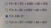
Consider the combinational circuit shown below, evaluate the outputs F2 as a function of the four inputs

Transcribed Image Text:O F2- B+
B'C +A'BD + AD + B'D
O F2-A+BC + A'BD' + AD + B'D
F2%3DA'B+ D'
O F2-A+B'C+A'BD' +
AD+B'D

Transcribed Image Text:Consider the combinational circuit shown below, Evaluate the outputs F2 as a function of the four inputs.
F1
T2
TA
F2
Expert Solution
This question has been solved!
Explore an expertly crafted, step-by-step solution for a thorough understanding of key concepts.
Step by stepSolved in 2 steps with 2 images

Knowledge Booster
Learn more about
Need a deep-dive on the concept behind this application? Look no further. Learn more about this topic, electrical-engineering and related others by exploring similar questions and additional content below.Similar questions
- Find the overall transfer Function of the following block diagram. Show complete solution.arrow_forwardThe counters are used in cascading in order to achieve the higher modulus operation. A certainapplication requires an overall modulus of 39,000 which can be achieved by placing the countersin cascading. You are requested to design a circuit for the said purpose by using 74HC161.arrow_forwardExplain the concept of supermodel and supermesh.please designas an example, two seperate circuits where they are required to solve the curcuitarrow_forward
- control theory elektrical and electronical engineeringarrow_forwardIn the circuit is a circuit that is only a little different to the one in the course notes, it has an extra resistor across the input V*. a non-inverting an inverting OpAmp -1.829V Vout R1 56k2 R3 180KO R2 150kO If we want to analyse this circuit, we need to know what effect that resistor has on the circuit. Let's begin with what you have been taught about circuit theory. The Vin and V+ are on the same node there is no resistance between them, and therefore the voltage on V* is -1.829 V. So, the resistor has no effect on our analysis. You see that R3 and R2 form a voltage divider - but how can we know this? What about the input V' of the OpAmp, wont it have an effect? The key is that there is no current into V- as the input resistance of an OpAmp inputs is on. This means all the current through R3 will go through R2, so it will have no effect on the voltage divider and can be excluded from our model. This means we can redraw the circuit like this. R2 V- R3 Vout (=Vin) OV Solve for: 1.…arrow_forwardQ2 Find the values of K and a so that the peak Overshoot for a step import is 25% and Peak time is 2 sec Rcs) K ک a 1 S Y(S)arrow_forward
- 3. Reduce the block diagram of the multi loop system shown in figure below. H₂(s) C R(S) C(s) G₁(s) ---G₂(s) G3(s) G4(s) H₁ (s) H3(s)arrow_forwardProblem 2-Design an OpAmp circuit that can perform the following operation v = (3v1 +5v2). Include the circuit and block diagram.arrow_forward2. Simplify the block diagram shown in Figure 2. Then, obtain the closed-loop transfer function C(s)lR(s). H3 R(s). C(s) G2 G3 G4 fa H H2 Figure 2arrow_forward
arrow_back_ios
SEE MORE QUESTIONS
arrow_forward_ios
Recommended textbooks for you
 Introductory Circuit Analysis (13th Edition)Electrical EngineeringISBN:9780133923605Author:Robert L. BoylestadPublisher:PEARSON
 Delmar's Standard Textbook Of ElectricityElectrical EngineeringISBN:9781337900348Author:Stephen L. HermanPublisher:Cengage Learning
 Programmable Logic ControllersElectrical EngineeringISBN:9780073373843Author:Frank D. PetruzellaPublisher:McGraw-Hill Education
 Fundamentals of Electric CircuitsElectrical EngineeringISBN:9780078028229Author:Charles K Alexander, Matthew SadikuPublisher:McGraw-Hill Education
 Electric Circuits. (11th Edition)Electrical EngineeringISBN:9780134746968Author:James W. Nilsson, Susan RiedelPublisher:PEARSON
 Engineering ElectromagneticsElectrical EngineeringISBN:9780078028151Author:Hayt, William H. (william Hart), Jr, BUCK, John A.Publisher:Mcgraw-hill Education,

Introductory Circuit Analysis (13th Edition)
Electrical Engineering
ISBN:9780133923605
Author:Robert L. Boylestad
Publisher:PEARSON

Delmar's Standard Textbook Of Electricity
Electrical Engineering
ISBN:9781337900348
Author:Stephen L. Herman
Publisher:Cengage Learning

Programmable Logic Controllers
Electrical Engineering
ISBN:9780073373843
Author:Frank D. Petruzella
Publisher:McGraw-Hill Education

Fundamentals of Electric Circuits
Electrical Engineering
ISBN:9780078028229
Author:Charles K Alexander, Matthew Sadiku
Publisher:McGraw-Hill Education

Electric Circuits. (11th Edition)
Electrical Engineering
ISBN:9780134746968
Author:James W. Nilsson, Susan Riedel
Publisher:PEARSON

Engineering Electromagnetics
Electrical Engineering
ISBN:9780078028151
Author:Hayt, William H. (william Hart), Jr, BUCK, John A.
Publisher:Mcgraw-hill Education,