Introductory Circuit Analysis (13th Edition)
13th Edition
ISBN: 9780133923605
Author: Robert L. Boylestad
Publisher: PEARSON
expand_more
expand_more
format_list_bulleted
Question
Only MATLAB code please

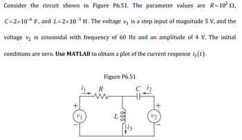
Transcribed Image Text:Consider the circuit shown in Figure P6.51. The parameter values are \( R = 10^3 \, \Omega \), \( C = 2 \times 10^{-6} \, \text{F} \), and \( L = 2 \times 10^{-3} \, \text{H} \). The voltage \( v_1 \) is a step input of magnitude 5 V, and the voltage \( v_2 \) is sinusoidal with a frequency of 60 Hz and an amplitude of 4 V. The initial conditions are zero. Use MATLAB to obtain a plot of the current response \( i_3(t) \).
**Figure P6.51:**
The diagram shows a series RLC circuit. It includes:
- A resistor (\( R \)) with a resistance of \( 10^3 \, \Omega \).
- An inductor (\( L \)) with an inductance of \( 2 \times 10^{-3} \, \text{H} \).
- A capacitor (\( C \)) with a capacitance of \( 2 \times 10^{-6} \, \text{F} \).
The circuit is powered by two voltage sources:
- \( v_1 \) (on the left side), which is a step input at 5 V.
- \( v_2 \) (on the right side), providing a sinusoidal input with a frequency of 60 Hz and amplitude of 4 V.
The currents \( i_1 \), \( i_2 \), and \( i_3 \) are shown at different points in the circuit, with \( i_3(t) \) being the current of interest to be plotted using MATLAB.
Expert Solution
This question has been solved!
Explore an expertly crafted, step-by-step solution for a thorough understanding of key concepts.
This is a popular solution
Trending nowThis is a popular solution!
Step by stepSolved in 3 steps with 3 images

Knowledge Booster
Similar questions
arrow_back_ios
arrow_forward_ios
Recommended textbooks for you
 Introductory Circuit Analysis (13th Edition)Electrical EngineeringISBN:9780133923605Author:Robert L. BoylestadPublisher:PEARSON
 Delmar's Standard Textbook Of ElectricityElectrical EngineeringISBN:9781337900348Author:Stephen L. HermanPublisher:Cengage Learning
 Programmable Logic ControllersElectrical EngineeringISBN:9780073373843Author:Frank D. PetruzellaPublisher:McGraw-Hill Education
 Fundamentals of Electric CircuitsElectrical EngineeringISBN:9780078028229Author:Charles K Alexander, Matthew SadikuPublisher:McGraw-Hill Education
 Electric Circuits. (11th Edition)Electrical EngineeringISBN:9780134746968Author:James W. Nilsson, Susan RiedelPublisher:PEARSON
 Engineering ElectromagneticsElectrical EngineeringISBN:9780078028151Author:Hayt, William H. (william Hart), Jr, BUCK, John A.Publisher:Mcgraw-hill Education,

Introductory Circuit Analysis (13th Edition)
Electrical Engineering
ISBN:9780133923605
Author:Robert L. Boylestad
Publisher:PEARSON

Delmar's Standard Textbook Of Electricity
Electrical Engineering
ISBN:9781337900348
Author:Stephen L. Herman
Publisher:Cengage Learning

Programmable Logic Controllers
Electrical Engineering
ISBN:9780073373843
Author:Frank D. Petruzella
Publisher:McGraw-Hill Education

Fundamentals of Electric Circuits
Electrical Engineering
ISBN:9780078028229
Author:Charles K Alexander, Matthew Sadiku
Publisher:McGraw-Hill Education

Electric Circuits. (11th Edition)
Electrical Engineering
ISBN:9780134746968
Author:James W. Nilsson, Susan Riedel
Publisher:PEARSON

Engineering Electromagnetics
Electrical Engineering
ISBN:9780078028151
Author:Hayt, William H. (william Hart), Jr, BUCK, John A.
Publisher:Mcgraw-hill Education,