Introductory Circuit Analysis (13th Edition)
13th Edition
ISBN: 9780133923605
Author: Robert L. Boylestad
Publisher: PEARSON
expand_more
expand_more
format_list_bulleted
Concept explainers
Question

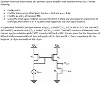
Transcribed Image Text:Consider the circuit shown below of a common source amplifier with a current mirror bias. Find the
following:
a. Find kp and kn.
b. Find the drain current of M2 given that IBIAS = 2mA and VouT = 2.5V.
c. Find the gm and r. of transistor M1.
d. Sketch the small signal model of transistor M3 (Hint: Is there any small signal in any terminal of
M3? If yes, then where is it? If no, then what happens to the small signal model?).
It is given that the NMOS (M1) parameters are H,Con = 3mA/V? , VTH,n = 0.5V and A = 0.02 and the PMOS
(M2 and M3) parameters are µ.Cox = 1mA/V? and VTH,p = -0.6V. The PMOS transistor M3 does not have
channel length modulation while PMOS transistor M2 has A = 0.02. It is also given that the dimensions of
M2 and M3 have equal widths of 5µm and lengths of L2 = 3µm and L3 = 1.5µm, respectively. M1 has
length of L1 = 1µm and width of W1 = 2µm.
5V
5V
M3
M2
VOUT
VIN
M1
IBIAS
Expert Solution
This question has been solved!
Explore an expertly crafted, step-by-step solution for a thorough understanding of key concepts.
This is a popular solution
Trending nowThis is a popular solution!
Step by stepSolved in 3 steps with 2 images

Knowledge Booster
Learn more about
Need a deep-dive on the concept behind this application? Look no further. Learn more about this topic, electrical-engineering and related others by exploring similar questions and additional content below.Similar questions
- b) For correct operation as an ac amplifier a npn BJT must be correctly DC biased to establish an appropriate Q-point, i.e a negative voltage VBC between the base and collector terminals and a positive voltage VBE between the base and emitter terminals. Figure 3.1 shows a circuit that can achieve this requirement. Explain the role of each resistive element in this circuit. Vin RB1 Cin HH iin RB2 + Rc VB RE + Vcc Vc Cout VE ww 11 Figure 3.1 th Vout Ce İoutarrow_forwardHand Calculation: Since you now have the values of R1 and R2 resistors, obtain numeric value of voltage gain Av=Vo/Vi, and numerical values of input and output resistances Ri and Ro. Note that you need to DC analysis first. Do a hand calculation and calculate the DC collector current or IC. This is needed in order to calculate the small signal parameters gm and rπ and in turn to obtain the Av , Ri and Ro Hence, first perform a DC analysis (use the circuit in Figure 1 and take all capacitors open) and assume your transistor has a β=140.arrow_forward2. A single transistor amplifier is shown in the circuit to the right. The input is a 100 kHz sine wave from a very low impedance source, with a 1 mV peak-to-peak amplitude. hfe, the forward current gain of the transistor, is 300. The base reverse leakage current is 1 nA. The ideality factor for the base-emitter diode is 2, so nkT= 50 mV. a. What are the voltages relative to ground and the currents flowing into, into, and out from the collector, the base, and the emitter, respectively? b. What is the impedance of the 1 µF capacitors at 100 kHz and what effect will this have on the gain of the amplifier? c. What is the gain of the amplifier and how does it depend on the hfe of the transistor? Luff Vin maits Ik { +V₁ = +15V املا Vo Sik Y 1 Fb V₂ I m Vout MF 2K = 250 hfő - -15V --Y₂arrow_forward
- Which of the following is the basic feature of the emitter-connected amplifier circuit? I. It has voltage gain II. It has current gain III. There is a 180 degree phase difference between the input signal and the output signalarrow_forward........ (Figure-1) R. RB= 380kN,Rc= 1kN B = 100, VBB = Vcc=12V RB ww Vec CC ......... I, V CE СЕ V ВЕ BB Q-1-b) Describe briefly the input / output characteristics and application of Common Emitter BJT Configurationarrow_forward
arrow_back_ios
arrow_forward_ios
Recommended textbooks for you
 Introductory Circuit Analysis (13th Edition)Electrical EngineeringISBN:9780133923605Author:Robert L. BoylestadPublisher:PEARSON
 Delmar's Standard Textbook Of ElectricityElectrical EngineeringISBN:9781337900348Author:Stephen L. HermanPublisher:Cengage Learning
 Programmable Logic ControllersElectrical EngineeringISBN:9780073373843Author:Frank D. PetruzellaPublisher:McGraw-Hill Education
 Fundamentals of Electric CircuitsElectrical EngineeringISBN:9780078028229Author:Charles K Alexander, Matthew SadikuPublisher:McGraw-Hill Education
 Electric Circuits. (11th Edition)Electrical EngineeringISBN:9780134746968Author:James W. Nilsson, Susan RiedelPublisher:PEARSON
 Engineering ElectromagneticsElectrical EngineeringISBN:9780078028151Author:Hayt, William H. (william Hart), Jr, BUCK, John A.Publisher:Mcgraw-hill Education,

Introductory Circuit Analysis (13th Edition)
Electrical Engineering
ISBN:9780133923605
Author:Robert L. Boylestad
Publisher:PEARSON

Delmar's Standard Textbook Of Electricity
Electrical Engineering
ISBN:9781337900348
Author:Stephen L. Herman
Publisher:Cengage Learning

Programmable Logic Controllers
Electrical Engineering
ISBN:9780073373843
Author:Frank D. Petruzella
Publisher:McGraw-Hill Education

Fundamentals of Electric Circuits
Electrical Engineering
ISBN:9780078028229
Author:Charles K Alexander, Matthew Sadiku
Publisher:McGraw-Hill Education

Electric Circuits. (11th Edition)
Electrical Engineering
ISBN:9780134746968
Author:James W. Nilsson, Susan Riedel
Publisher:PEARSON

Engineering Electromagnetics
Electrical Engineering
ISBN:9780078028151
Author:Hayt, William H. (william Hart), Jr, BUCK, John A.
Publisher:Mcgraw-hill Education,