
Introductory Circuit Analysis (13th Edition)
13th Edition
ISBN: 9780133923605
Author: Robert L. Boylestad
Publisher: PEARSON
expand_more
expand_more
format_list_bulleted
Related questions
Question
Consider the circuit diagram below. Compute the impedances for all circuit
components,
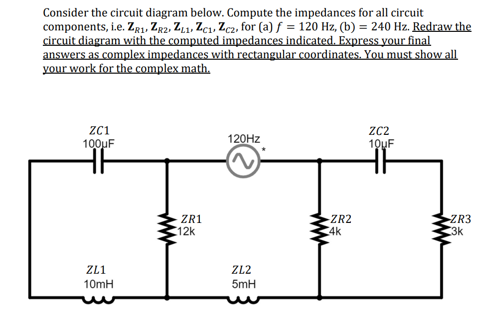

Transcribed Image Text:Consider the circuit diagram below. Compute the impedances for all circuit
components, i.e. ZR1, ZR2, ZL1, Zc₁, Zc2, for (a) f = 120 Hz, (b) = 240 Hz. Redraw the
circuit diagram with the computed impedances indicated. Express your final
answers as complex impedances with rectangular coordinates. You must show all
your work for the complex math.
ZC1
100μF
HF
ZL1
10mH
ZR1
12k
120Hz
ZL2
5mH
-ZR2
4k
ZC2
10uF
ZR3
3k
Expert Solution
This question has been solved!
Explore an expertly crafted, step-by-step solution for a thorough understanding of key concepts.

Step by stepSolved in 1 steps with 4 images

Knowledge Booster

Similar questions
- 6. PLEASE PROVIDE HANDWRITTEN SOLUTIONS. THANK YOU!arrow_forwardQ8) For the circuit shown in Figure below,a=90:- A) Plot V load waveform showing all its dimensions. Calculate I load mean. B) 220 * R=10 E-155.5V Vloadarrow_forwardQ3: . Q2:For the network shown in figure,determine the input impedance, output impedance,voltage gain,current gain and source voltage gain by using complete hybrid equivalent model if hie=1.6Ko, Ire=2*10, hr=110 and hoe=20us. 20 V 2.2 k Ohm 50 k Ohm 10 uF HH 1.1 k Ohm 10 UF 30 uF HE 50 k Ohm 3.3 k Ohmarrow_forward
- Can you explain in detail on how to solve this?Determine current ID graphically using load line analysis, if Zener voltage is 3V.arrow_forward4.10 A dc-dc converter is connected to a 100 V d.c. source to supply an inductive load having 40 mH in series with 5 2 resistance. FWD is placed across the load. Load current varies between two limits of 10 A and 12 A. (a) Find the time ratio (duty cycle) and the frequency of the chopper. (b) Find the equivalent Thevenin resistance across the source and determine the average source current.arrow_forwardWhich one of the following statements is true: The purpose of the power-factor correction is to add inductive elements to keep real power at a minimum level. The purpose of the power-factor correction is to add resistive elements (typically resistances) to improve the total reactive power. The purpose of the power-factor correction is to add reactive components (typically capacitive) to establish a system power factor closer to unity. The purpose of the power-factor correction is to add resistive elements (typically resistances) to establish a system power factor closer to zero.arrow_forward
arrow_back_ios
arrow_forward_ios
Recommended textbooks for you
- Introductory Circuit Analysis (13th Edition)Electrical EngineeringISBN:9780133923605Author:Robert L. BoylestadPublisher:PEARSON
 Delmar's Standard Textbook Of ElectricityElectrical EngineeringISBN:9781337900348Author:Stephen L. HermanPublisher:Cengage Learning
 Programmable Logic ControllersElectrical EngineeringISBN:9780073373843Author:Frank D. PetruzellaPublisher:McGraw-Hill Education
  Fundamentals of Electric CircuitsElectrical EngineeringISBN:9780078028229Author:Charles K Alexander, Matthew SadikuPublisher:McGraw-Hill Education
 Electric Circuits. (11th Edition)Electrical EngineeringISBN:9780134746968Author:James W. Nilsson, Susan RiedelPublisher:PEARSON
 Engineering ElectromagneticsElectrical EngineeringISBN:9780078028151Author:Hayt, William H. (william Hart), Jr, BUCK, John A.Publisher:Mcgraw-hill Education,
Introductory Circuit Analysis (13th Edition)
Electrical Engineering
ISBN:9780133923605
Author:Robert L. Boylestad
Publisher:PEARSON
Delmar's Standard Textbook Of Electricity
Electrical Engineering
ISBN:9781337900348
Author:Stephen L. Herman
Publisher:Cengage Learning
Programmable Logic Controllers
Electrical Engineering
ISBN:9780073373843
Author:Frank D. Petruzella
Publisher:McGraw-Hill Education
Fundamentals of Electric Circuits
Electrical Engineering
ISBN:9780078028229
Author:Charles K Alexander, Matthew Sadiku
Publisher:McGraw-Hill Education
Electric Circuits. (11th Edition)
Electrical Engineering
ISBN:9780134746968
Author:James W. Nilsson, Susan Riedel
Publisher:PEARSON
Engineering Electromagnetics
Electrical Engineering
ISBN:9780078028151
Author:Hayt, William H. (william Hart), Jr, BUCK, John A.
Publisher:Mcgraw-hill Education,