Elements Of Electromagnetics
7th Edition
ISBN: 9780190698614
Author: Sadiku, Matthew N. O.
Publisher: Oxford University Press
expand_more
expand_more
format_list_bulleted
Concept explainers
Question
2 PARTs (A &B)- SOLVE CAREFULLY!! Please Write Clearly and Box the final Answer(s)
( Use images Below - Pay attention to numbers given)

Transcribed Image Text:The diagram depicts a simplified representation of a four-stroke combustion engine cycle, typically found in internal combustion engines.
1. **Intake Stroke (Labeled "1")**:
- The intake stroke begins when the piston moves down the cylinder's bore from top dead center (TDC) to bottom dead center (BDC).
- This movement creates a vacuum that allows the air-fuel mixture to enter the cylinder through the intake valve.
2. **Compression Stroke (Labeled "2")**:
- During the compression stroke, the piston moves back up the bore from BDC to TDC.
- The air-fuel mixture is compressed in the cylinder, increasing its temperature and pressure.
3. **Power Stroke (Labeled "3")**:
- The power stroke starts with the ignition of the compressed air-fuel mixture by a spark plug (in gasoline engines) or by the heat of compression (in diesel engines).
- The combustion generates a significant explosion and force, pushing the piston down from TDC to BDC.
4. **Exhaust Stroke (Labeled "4")**:
- During the exhaust stroke, the piston moves back up the cylinder from BDC to TDC.
- This movement expels the burnt gases from the combustion chamber through the exhaust valve, allowing the cycle to begin anew with the intake stroke.
The engine cycle is a continuous process, repeated consistently to convert fuel into mechanical energy, powering the vehicle.

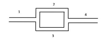
Transcribed Image Text:Consider a simple network of blood vessels shown in the figure. Segment 1 has a diameter of 1 cm, whereas segments 2, 3, and 4 have a diameter of 0.25 cm. All the segments have a length of 10 cm.
(a) If the total pressure drop Δp between the inlet and outlet is 100 mmHg, compute the blood flow rates in each segment, assuming representative values for whole blood viscosity and density.
(b) If the diameter of segment 2 is reduced to 0.22 cm, compute the new flow rates through each of the segments.
(Assume blood viscosity μ = 3.5 cP and density 1.060 g/cm³ and laminar flow.)
Expert Solution
This question has been solved!
Explore an expertly crafted, step-by-step solution for a thorough understanding of key concepts.
This is a popular solution
Trending nowThis is a popular solution!
Step by stepSolved in 6 steps

Knowledge Booster
Learn more about
Need a deep-dive on the concept behind this application? Look no further. Learn more about this topic, mechanical-engineering and related others by exploring similar questions and additional content below.Similar questions
- Q1: (20 marks) Write in summarat vou know abou fun me taleoems calculus. (20 marks) secondarrow_forwardOz Lawn Care Inc. manufactures and assembles lawnmowers that are shipped to dealers throughout the United States and Canada. Two different procedures have been proposed for mounting the engine on the frame of the lawnmower. PB (Minutes) UPB (Minutes )345798632 5 Is there a difference in the methods' mean time to mount the engines on the frames of the lawnmowers? The answer must be in handwriting. Please write your answer using a ball - point pen on plain paper. Submit your homework by uploading it to the canvas. Good Luck!arrow_forward
Recommended textbooks for you
 Elements Of ElectromagneticsMechanical EngineeringISBN:9780190698614Author:Sadiku, Matthew N. O.Publisher:Oxford University Press
 Mechanics of Materials (10th Edition)Mechanical EngineeringISBN:9780134319650Author:Russell C. HibbelerPublisher:PEARSON
 Thermodynamics: An Engineering ApproachMechanical EngineeringISBN:9781259822674Author:Yunus A. Cengel Dr., Michael A. BolesPublisher:McGraw-Hill Education
 Control Systems EngineeringMechanical EngineeringISBN:9781118170519Author:Norman S. NisePublisher:WILEY
 Mechanics of Materials (MindTap Course List)Mechanical EngineeringISBN:9781337093347Author:Barry J. Goodno, James M. GerePublisher:Cengage Learning
 Engineering Mechanics: StaticsMechanical EngineeringISBN:9781118807330Author:James L. Meriam, L. G. Kraige, J. N. BoltonPublisher:WILEY

Elements Of Electromagnetics
Mechanical Engineering
ISBN:9780190698614
Author:Sadiku, Matthew N. O.
Publisher:Oxford University Press

Mechanics of Materials (10th Edition)
Mechanical Engineering
ISBN:9780134319650
Author:Russell C. Hibbeler
Publisher:PEARSON

Thermodynamics: An Engineering Approach
Mechanical Engineering
ISBN:9781259822674
Author:Yunus A. Cengel Dr., Michael A. Boles
Publisher:McGraw-Hill Education

Control Systems Engineering
Mechanical Engineering
ISBN:9781118170519
Author:Norman S. Nise
Publisher:WILEY

Mechanics of Materials (MindTap Course List)
Mechanical Engineering
ISBN:9781337093347
Author:Barry J. Goodno, James M. Gere
Publisher:Cengage Learning

Engineering Mechanics: Statics
Mechanical Engineering
ISBN:9781118807330
Author:James L. Meriam, L. G. Kraige, J. N. Bolton
Publisher:WILEY