Elements Of Electromagnetics
7th Edition
ISBN: 9780190698614
Author: Sadiku, Matthew N. O.
Publisher: Oxford University Press
expand_more
expand_more
format_list_bulleted
Concept explainers
Question
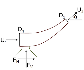
Consider a reducer with inlet and outlet diameters of D1 and D2, respectively. The respective
velocities are U1 and U2, as shown below. The fluid of density, ρ exits at an angle θ with respect
to the horizontal plane. The input is along the horizontal plane. Assume no viscous effects, i.e., μ
= 0.
Calculate the (i) vertical, and (ii) horizontal forces to hold the reducer stationary.
Consider the following:
• Mass balance
• Energy balance
• Momentum balance in horizontal direction
• Momentum balance in vertical direction

Transcribed Image Text:The image depicts a fluid dynamics diagram illustrating the flow through an elbow pipe.
- **Flow Direction**: The flow enters with velocity \( U_1 \) in a horizontal direction and exits with velocity \( U_2 \) at an angle \( \theta \).
- **Pipe Dimensions**:
- \( D_1 \): Diameter of the pipe at the inlet.
- \( D_2 \): Diameter of the pipe at the outlet.
- **Force Components**:
- \( F_H \): Horizontal force component.
- \( F_V \): Vertical force component.
- **Angle of Deflection**: The angle \( \theta \) indicates the deflection of flow at the outlet compared to the inlet.
This diagram serves to visualize the alteration in flow direction and velocity as fluid moves through the elbow, and the resulting forces that develop from this change.
Expert Solution
This question has been solved!
Explore an expertly crafted, step-by-step solution for a thorough understanding of key concepts.
This is a popular solution
Trending nowThis is a popular solution!
Step by stepSolved in 2 steps

Follow-up Questions
Read through expert solutions to related follow-up questions below.
Follow-up Question
Where is the Energy Balance?
Solution
by Bartleby Expert
Follow-up Questions
Read through expert solutions to related follow-up questions below.
Follow-up Question
Where is the Energy Balance?
Solution
by Bartleby Expert
Knowledge Booster
Learn more about
Need a deep-dive on the concept behind this application? Look no further. Learn more about this topic, mechanical-engineering and related others by exploring similar questions and additional content below.Similar questions
- Your team is designing a chemical processing plant. You are the liquid handling and transportation specialist, and you need to transport a solvent (μ = 3.1 cP, ρ = 122k kg/m3) from a storage tank to a reaction vessel. Due to other equipment constraints, the fluid velocity must be 0.8 m/sec, and you must use stainless steel piping (ε = 0.00015 mm) with a total length (L) of 12 m. Determine the pipe inner diameter (ID) you will need to achieve a pressure drop of 0.3 kPa. Use the Moody chart.arrow_forwardProblem Consider a cylindrical pipe of length L and diameter D = 2R. The angle that the axis of the pipe forms with the vertical direction is a. Assume that when the fluid enters the pipe its velocity is uniform (i.e., it has the same value over the entire cross-section of the pipe) and equal to U in the axial direction. In the radial and angular directions, the velocity is zero. So, it is: 2 =0: v(r, 0, 2) = Ue, (1.1) Here v is the fluid velocity and e, is a vector of unit magnitude parallel to the coordinate axis z; furthermore, we have assumed that the pipe inlet is located at z = 0. Near the entrance of the pipe, the velocity profile varies in the axial direction. But after a certain entrance length, the profile becomes fully developed, no longer changing with z. The evolution of the velocity profile is sketched in Fig. 1, where, for clarity, the pipe inclination is not shown. The entrance length is denoted by L.. For z > L., the fluid velocity is no longer a function of the axial…arrow_forwardThe diameter of a pipe changes gradually from 75 mm at a point A, 6 m above datum, to 150 mm at B, 3 m above datum. The pressure at A is 103 kPa and the velocity of flow is 3.6 m/s. Neglecting losses, with the aid of a neat sketch, determine the pressure at Barrow_forward
- Don't provide the wrong solution, Humble request.arrow_forwardSection 1 is the image below the problemarrow_forwardWater steam is running through the nozzle. Inlet pressure is P1=25 bars; T1=300C; V1=90m/s; A1=0.2m2. The exit parameters are: P2=11bars; T2=210C. The mass flow rate is m=2 kg/s. Determine: a.Exit velocity V2=?; b.Inlet and outlet diameters D1 and D2.arrow_forward
arrow_back_ios
arrow_forward_ios
Recommended textbooks for you
 Elements Of ElectromagneticsMechanical EngineeringISBN:9780190698614Author:Sadiku, Matthew N. O.Publisher:Oxford University Press
 Mechanics of Materials (10th Edition)Mechanical EngineeringISBN:9780134319650Author:Russell C. HibbelerPublisher:PEARSON
 Thermodynamics: An Engineering ApproachMechanical EngineeringISBN:9781259822674Author:Yunus A. Cengel Dr., Michael A. BolesPublisher:McGraw-Hill Education
 Control Systems EngineeringMechanical EngineeringISBN:9781118170519Author:Norman S. NisePublisher:WILEY
 Mechanics of Materials (MindTap Course List)Mechanical EngineeringISBN:9781337093347Author:Barry J. Goodno, James M. GerePublisher:Cengage Learning
 Engineering Mechanics: StaticsMechanical EngineeringISBN:9781118807330Author:James L. Meriam, L. G. Kraige, J. N. BoltonPublisher:WILEY

Elements Of Electromagnetics
Mechanical Engineering
ISBN:9780190698614
Author:Sadiku, Matthew N. O.
Publisher:Oxford University Press

Mechanics of Materials (10th Edition)
Mechanical Engineering
ISBN:9780134319650
Author:Russell C. Hibbeler
Publisher:PEARSON

Thermodynamics: An Engineering Approach
Mechanical Engineering
ISBN:9781259822674
Author:Yunus A. Cengel Dr., Michael A. Boles
Publisher:McGraw-Hill Education

Control Systems Engineering
Mechanical Engineering
ISBN:9781118170519
Author:Norman S. Nise
Publisher:WILEY

Mechanics of Materials (MindTap Course List)
Mechanical Engineering
ISBN:9781337093347
Author:Barry J. Goodno, James M. Gere
Publisher:Cengage Learning

Engineering Mechanics: Statics
Mechanical Engineering
ISBN:9781118807330
Author:James L. Meriam, L. G. Kraige, J. N. Bolton
Publisher:WILEY